Download
1 / 74
760 likes | 1.02k Views
Analog Electronics Class Session 1: RC and RL Circuits (Into to Tina Spice). Sep 1, 2011. Intro to the Class. Class 1: Review RC, and RL Circuits Class 2: Ideal op-amp, Analysis Techniques Class 3: Vosi, Vcm, CMRR, PSRR, Class 4: Aol, Ib, Drift, Output swing Class 5: Power….

E N D
Analog Electronics ClassSession 1: RC and RL Circuits(Into to Tina Spice) Sep 1, 2011
Intro to the Class Class 1: Review RC, and RL Circuits Class 2: Ideal op-amp, Analysis Techniques Class 3: Vosi, Vcm, CMRR, PSRR, Class 4: Aol, Ib, Drift, Output swing Class 5: Power…. Class 6: Noise… This will probably change
Goal of Class • Intuitive view of analog electronics • Quick analysis by inspection • Use of spice tools • Cover practical considerations • Example: Capacitor temperature drift, voltage coefficients • Fill in gaps in knowledge
Capacitor Transient Analysis
Instantaneous changes on capacitor voltage are not possible! This would create infinite current.
Application – Charging Input cap A simple RC is sometimes used to condition the input to an A/D converter. The table shows the delay required to settle to ½ bit.
Tina Spice – Transient Analysis Transient Analysis: Looks at signals vs. time. Set the Source: In this example we will use a step input to change the input from 0V to 1V
Press the button to edit the signal. Choose the amplitude and start time. In this example 1V and 1mS.
This is the result Use separate curves
Use the curser to check the specific points on the curve. In this case 1 time constant yields 0.625V as expected.
Capacitor AC Analysis
Capacitance at dc and High Frequency Open at Low Frequency and DC Short at High Frequency
Voltage Divider for RC circuit • At low frequencies the output is equal to the input. • At High frequencies the output is zero (shorted)
Decibels (dB) • NdB = 20 log (Gain) = 20 log (Vout / Vin) • 20Log(1) = 0, • 20Log(10) = 20 • 20Log(100) = 40 • 20Log(0.1) = -20 • 20Log(0.01) = -40 • Log(0) is not defined • Gain = 10(Ndb/20)
After pole decrease Gain by 20db/dec After zero increase Gain by 20db/dec One decade before and after pole phase decreases by -45o/decade One decade before and after zero phase increases by 45o/decade Bode Plot
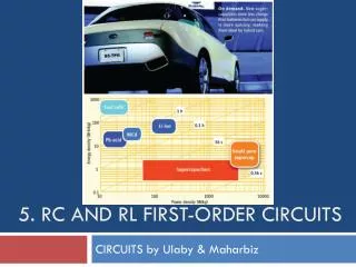
Inductor Transient Analysis
Transient Simulation for RL Circuits Change the prosperities of the switch to close and open to demonstrate charge / discharge.
S1 Closed -- Initial Voltage During Charge through R1 S1 Open – Discharge through R2
Inductor AC Analysis
Inductance at dc and High Frequency Short at Low Frequency and DC Open at High Frequency
Voltage Divider for LR circuit • At low frequencies the output is zero. • At High frequencies the output is equal to the input