Download

1 / 60
1.25k likes | 2.03k Views
The IS-IS Protocol. SAvPS Genci. References. Intermediate System-to-Intermediate System Protocol www.cisco.com CNAP presentation Presentation of P. Paluch (fri.utc.sk). Reasons why to u ses IS-IS Routing. Large ISPs Stable protocol

E N D
The IS-IS Protocol SAvPS Genci
References • Intermediate System-to-Intermediate System Protocol www.cisco.com • CNAP presentation • Presentation of P. Paluch (fri.utc.sk)
Reasons why to uses IS-IS Routing Large ISPs • Stable protocol • Originally deployed by ISPs because US government mandated internet support of OSI and IP
Úvod do OSI sietí • Na prelome 70. a 80. rokov 20. storočia sa vývoj uberaldvomi smermi: • US Department of Defense vyvíjal tzv. Network Control Program,ktorý bol neskôr nahradený súčasnou sadou protokolov TCP/IP • ISO sa snažila vytvoriť a štandardizovať vlastnú sadu protokolov –tzv. OSI stack, ktorý zodpovedá známemu RM ISO OSI • Zatiaľčo pragmatici programujúci TCP/IPjednoduchosťou a prehľadnosťou protokolu uspeli, ISOsa zdržovala vytváraním formálnych, komplexných aabstraktných protokolov a rozhraní medzi nimi • Protokoly ISO sú pomerne komplikované, ich štandardizácia sa dlhýcas vliekla • ISO protokoly dodnes možno nájsť v sieťach telekomunikačnýchoperátorov, avšak masové nasadenie ISO protokolov nikdynenastalo
Úvod do OSI sietí • Pre OSI siete boli navrhnuté niekolké smerovacie protokoly: • ES-IS: komunikácia medzi stanicou a jej bránou • IS-IS: komunikácia medzi routermi v jednom autonómnom systéme (v ISO terminológii „doména“) • IDRP: komunikácia medzi doménami (analóg BGP) • Vlastnosti IS-IS sa ukázali ako dobré a premyslené • IS-IS bol navrhovaný a funkcný skôr než OSPF a OSPF štartovalo ako lahký odvar IS-IS • Pri migrácii existujúcich OSI sietí na IP bolo vhodnejšie mat protokol, ktorý dokáže naraz slúžit aj pre OSI, aj pre IP • Do IS-IS boli v RFC 1195 dodefinované rozšírenia pre spoluprácu s IP svetom, sémantika protokolu však zostala
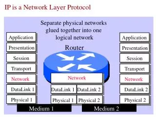
ISO OSI Connectionless Network Service • OSI CLNS (Connectionless Network Service) is a network layer service similar to the IP service. • A CLNS entity communicates over Connectionless Network Protocol (CLNP) with its peer CLNS entity. • Routers are ISs, and hosts are End Systems (ESs). • ESs themselves have no routing information; • they discover ISs (routers) by listening to Intermediate System Hellos (ISHs) and sending traffic to any random router. • ESs send End System Hellos (ESHs); • they do not choose a designated router to handle all traffic, • optimal routing is accomplished via redirects
ISO Addressing • CLNS addresses that are used by routers are called network service access points (NSAPs) • NSAP addresses have a size from 8 to 20 bytes • NSAP address contains OSI address of the device and link to the higher layer process
Network Entity Title (NET Address) • NSAP addresses have a one-octet NSEL field that identifies a process on the device • NET addresses are NSAP addresses with an NSEL value of 0
IS-IS Routing • IS = router • IS-IS was originally designed as the IGP for the Connectionless Network Service (CLNS), part of the OSI protocol suite. • The OSI protocol suite layer 3 protocol is the Connectionless Network Protocol (CLNP). • IS-IS uses CLNS addresses to identify routers and build the LSDB.
IS-IS Features • Link-state routing protocol • Supports VLSM • Uses Dijkstra’s SPF algorithm; has fast convergence • Uses Hellos to establish adjacencies and LSPs to exchange link-state information • Efficient use of bandwidth, memory, and processor • Supports two routing levels: • Level 1: Builds common topology of system IDs in local area and routes within area using lowest cost path. • Level 2: Exchanges prefix information (area addresses) between areas. Routes traffic to area using lowest-cost path.
IS-IS Link-State Operation • Routers identified as Level 1, Level 2, or Level 1-2: • Level 1 routers use LSPs to build topology for local area. • Level 2 routers use LSPs to build topology between different areas. • Level 1-2 routers act as border routers between Level 1 and Level 2 routing domains.
Integrated IS-IS Routing • Integrated IS-IS is IS-IS for multiple protocols: • For IP, CLNS, or both • Uses its own PDUs to transport IP routing information; updates are not sent in IP packets. • Requires CLNS addresses, even if only routing for IP.
Integrated IS-IS Design Principles • IP and CLNP addressesmust be planned. • Use two-level hierarchy for scalability: • Limits LSP flooding • Provides opportunity for summarization • Summarization: • Limits update traffic • Minimizes router memory and CPU usages
Issues with Integrated IS-IS • Default narrow metrics are limited to 6-bit interface and 10-bit path metric: • In Cisco IOS 12.0, wide metrics allow 24-bit interface and 32-bit path metric. • Cisco IOS software has default metric of 10 on all interfaces.
End System-to-Intermediate System • ES-IS forms adjacencies between ESs and routers (ISs). IP end-systems don’t use ES-IS • ESs transmit ESHs to announce their presence to ISs. • ISs transmit ISHs to announce their presence to ESs. • ISs transmit IIHs to other ISs.
Similarities Between IS-IS and OSPF • Integrated IS-IS and OSPF are both open standard link-state protocols with the following similar features: • Link-state representation, aging timers, and LSDB synchronization • SPF algorithms • Update, decision, and flooding processes • VLSM support • Scalability of link-state protocols has been proven (used in ISP backbones). • They both converge quickly after changes.
Integrated IS-IS vs. OSPF: Area Design • OSPF is based on a central backbone with all areas attached to it. In OSPF the border is inside routers (ABRs) Each link belongs to one area
Advantages of Integrated IS-IS • Supports CLNP and IP • More extensible through TLV design
Advantages of OSPF • OSPF has more features, including: Has three area types: normal, stub, and NSSA Defaults to scaled metric (IS-IS always 10) • OSPF is supported by many vendors. • Information, examples, and experienced engineers are easier to find.
Comparison of Integrated IS-IS and OSPF The following table summarizes the differences between OSPF and integrated IS-IS.
The IS-IS Protocol BSCI Module 4 Lesson 3 Configuring Basic Integrated IS-IS
OSI Area Routing: Building an OSI Forwarding Database (Routing Table) • When databases are synchronized, Dijkstra’s algorithm (SPF) is run on the LSDB to calculate the SPF tree. • The shortest path to the destination is the lowest total sum of metrics. • Separate route calculations are made for Level 1 and Level 2 routes in Level 1-2 routers. • Best paths are placed in the OSI forwarding database (CLNS routing table).
Building an IP Routing Table • Partial Route Calculation (PRC) is run to calculate reachability. • Since IP and ES are represented as leaf objects, they donot participate in SPF. • Best paths are placed in the IP routing table following IP preferential rules. • They appear as Level 1 or Level 2 IP routes.
Integrated IS-IS Configuration Steps • Define areas, prepare addressing plan (NETs) for routers, and determine interfaces. • Enable IS-IS on the router. • Configure the NET. • Enable Integrated IS-IS on the appropriate interfaces. Do not forget interfaces to stub IP networks, such as loopback interfaces (although there are no CLNS neighbors there). • These are each explained in the next few slides.
Step 1: Define Area and Addressing • Area determined by NET prefix: • Assign to support two-level hierarchy. • Addressing: • IP:Plan to support summarization. • CLNS: Prefix denotes area. System ID must be unique.
Step 2: Enable IS-IS on the Router router(config)# router isis [area-tag] • Enable the IS-IS routing protocol. • area-tag– name for a process • When routing of CLNS packets is also needed, use the clns routing command.
Step 3: Configure the NET Router(config-router)# net network-entity-title • Configure an IS-IS NET address for the routing process.
Step 4: Enable Integrated IS-IS router(config-if)# ip router isis [area-tag] • Includes an interface in an IS-IS routing process
Simple Integrated IS-IS Example The configured router acts as an IP-only Level 1-2 router. interface FastEthernet0/0 ip address 10.1.1.2 255.255.255.0 ip router isis ! interface Serial 0/0/1 ip address 10.2.2.2 255.255.255.0 ip router isis ! <output omitted> router isis net 49.0001.0000.0000.0002.00
Change IS-IS Router Level Router(config-router)# is-type {level-1 | level-1-2 | level-2-only} • Configure the IS-IS level globally on a router; the default is level 1-2.
Change IS-IS Interface Level Router(config-if)# isis circuit-type {level-1 | level-1-2 | level-2-only} • Configure the type of adjacency on an interface; the default is Level 1-2.
Change IS-IS Metric Router(config-if)# isis metric metric [delay-metric[expense-metric [error-metric]]]{level-1 | level-2} • Configure the metric for an interface; the default is 10. • Metric value is from 1 to 63. Router(config-router)# metric default-value{level-1 | level-2} • Alternately, configure the metric globally for all interfaces.
Example: Tuning IS-IS Configuration • Change router type on R1 and R3 • Change interface levels on R2 • Change metric on S0/0/1
IP Summarization Router(config-router)# summary-address address mask [level-1 | level-2 |level-1-2][tag tag-number] [metric metric-value] • Creates summary • Default is Level 2 Example: P3R1(config-router)# summary-address 10.3.2.0 255.255.254.0 level-1-2 • Summarizes 10.3.2.0/23 into Level 1-2
Example: Is Integrated IS-IS Running? R2#show ip protocols Routing Protocol is "isis" Invalid after 0 seconds, hold down 0, flushed after 0 Outgoing update filter list for all interfaces is not set Incoming update filter list for all interfaces is not set Redistributing: isis Address Summarization: None Maximum path: 4 Routing for Networks: FastEthernet0/0 Loopback0 Serial0/0/1 Routing Information Sources: Gateway Distance Last Update 10.10.10.10 115 00:00:02 10.30.30.30 115 00:00:03 Distance: (default is 115) • Displays the parameters and current state of the active routing protocol processes
Example: Are There Any IP Routes? router# show ip route [address [mask]] | [protocol [process-id]] R2#show ip route isis 10.0.0.0/24 is subnetted, 5 subnets i L2 10.30.30.0 [115/45] via 10.2.2.3, Serial0/0/1 i L1 10.10.10.0 [115/20] via 10.1.1.1, FastEthernet0/0 R2# • Displays the current state of the routing table
TroubleshootingCommands: CLNS Router# show clns • Displays information about the CLNS network Router# show clns [area-tag] protocol • Lists the protocol-specific information Router# show clns interface [typenumber] • Lists the CLNS-specific information about each interface Router# show clns [area-tag] neighbors [type number] [detail] • Displays both ES and IS neighbors
TroubleshootingCommands: CLNS and IS-IS Router# show isis [area-tag] route • DisplaysIS-IS Level 1 routing table (system IDs) Router# show clns route [nsap] • Displays IS-IS routing table (areas) Router# show isis [area-tag] database • Displaysthe IS-IS LSDB Router# show isis [area-tag] topology • Displays IS-IS least-cost paths to destinations
Example: OSI Intra-Area andInterarea Routing Routing in a Two-Level Area Structure