Download
1 / 23
230 likes | 746 Views
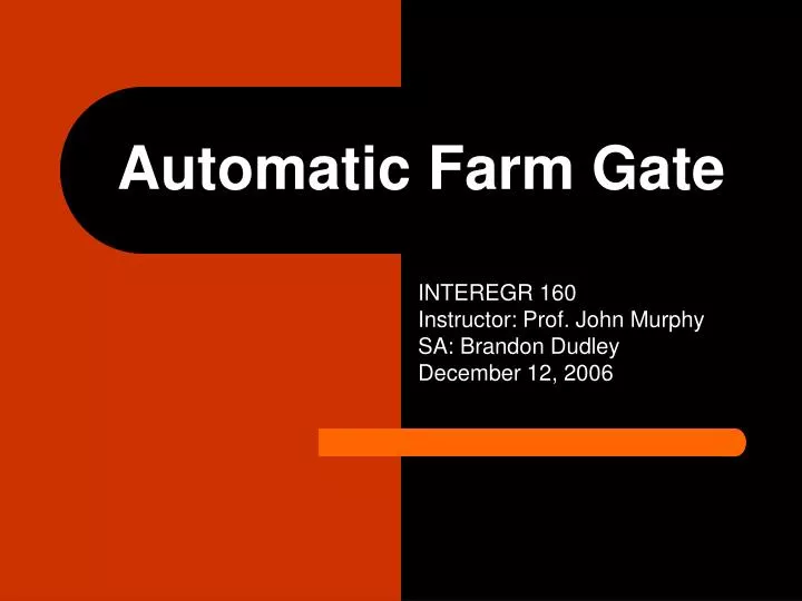
Automatic Farm Gate. INTEREGR 160 Instructor: Prof. John Murphy SA: Brandon Dudley December 12, 2006. Background Problem Statement Gantt Chart Brainstorming Preliminary Designs Evaluation. Integrated Design Construction & Materials Testing Budget Alternative Design Summary.

E N D
Automatic Farm Gate INTEREGR 160 Instructor: Prof. John Murphy SA: Brandon Dudley December 12, 2006
Background Problem Statement Gantt Chart Brainstorming Preliminary Designs Evaluation Integrated Design Construction & Materials Testing Budget Alternative Design Summary Outline
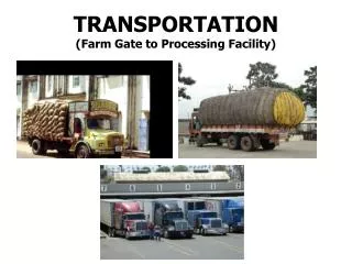
Background Information • Mark Novak and AgrAbility Project • America’s aging farming populations need labor-saving devices to assist their everyday task • Currently, farm gate must be opened manually after exiting a vehicle • Current products in the market are unsatisfactory (expensive and must be bought as a package with a new gate)
Problem Statement Our goal is to design an automated gate to meet the needs of the aging and disabled farming population. The gate will be remotely opened and closed to reduce the amount of physical labor required to operate the gate. We will be providing the farmers with a safer, inexpensive, and reliable system that can be easily constructed and operated
Sliding gate Swinging gate Drop down gate Flip down gate Lamborghini (pivot) gate Double swinging gate Wheeled gate Rotating gate Solar powered Pulley system Gear motored Screw drive powered Magnetic lock Ground switch Rechargeable battery Rotary powered Gates of fire Brainstorming – Small Group and Big Group
Preliminary Small Teams’ Design • Screw drive powered sliding gate • Sliding gate powered by spring loaded wheels • Rack and pinion sliding gate • Geared power swinging gate
Safety Durability Reliability Accessibility Simplicity Cost Time Serviceability Adaptability Manual Operation Evaluation Criteria
Integrated Design & Prototype • A swinging gate powered by a motorized wheel attached to the gate • Motorized wheel bought from Tecel • Spring loaded shock system attached to the wheel to accommodate rough terrains • A solenoid powered latch • ½ scale prototype (3 ft x 8 ft) • Radio receiver and transmitter to apply power and switch direction of motor
Material & Budget Breakdown • PVC’s (Home Depot) – Total: $27.63 • 5 - 10 ft, 1 inch PVC pipes • 4 - 1 inch L connectors • 8 – 1 inch T connectors • 3 – 1 inch X connectors • 2 Gate Hinges (Ace Hardware): $10 • Gate attachment • Support attachment • 6 Bolts (3/8 inches course) • 2 nuts (3/8 inches course) • Nuts & Bolts (Ace Hardware): $18.17 • 4 guidance bolts • 2 stabilizer bolts • 1 threaded U bolt • 8 nuts • 8 washers • 3 fine thread bolts
Material & Budget Breakdown cont. • Tubular Solenoid, Pull Type, 1.00” (25 mm) DIA X 2.00” (51 mm) L; 12 DC volts; continuous cycle (ElectroMechanicsOnline): $47.82 • 2 Channel Rolling Code RF Remote and Receiver (Car’s Electronics): $45.00 • Continuous – Length Compression Springs (McMaster – Carr): $14.51 – UNUSED • 2 Way Lockable Gate Latch (Northern Tool + Equipment): $27.53 – UNUSED • Motorized Wheel 7 inches diameter (TECEL): $48.00 • Radioshack Electrical Supplies: Total $22.96 • 2 DPDT 10Amp 12 VDC Relays • ½ Amp Slow Blow Fuse • 5 Amp Slow Blow Fuse • 2 Kill Switches (Amazon.com): $9.98 – UNUSED • Battery • Latches assembly • 1 – 1” washer • 1/8” x ¼” x 4 3/8” metal bar • Wheel Attachment Aseembly • 3 metal plates • 1 spring 2 inches diameter
Total Budget • Total spent: $271. 60 • Total used on prototype: $219.57 • Theoretical budget for user: ~ $100.00 - $200.00* *Battery sold separately
Constructions • Order of materials • PVC gate construction • Spring loaded shock system construction • Attachment of motorized wheel to the shock system • Development of electrical details • Development of latching mechanism • Full assembly
Electronics • Powered by 12V automobile battery • Two channel radio transmitter/receiver • Radio signals activate relays, allowing current to power the motor and latch • Signal 1 trips relay 1, allowing current to flow in one direction • Signal 2 trips relay 2, allowing current to flow in the opposite direction
Design’s Advantages • Only simple modification needed to be done on the existing gate • Less chances of physical injury (compared to gear or pulley system) • Works in various terrains • Can be manually opened in case of power outage • Only require small power (enough to be powered by a battery)
Testing • Preliminary computations to prevent later problems • Testing on the remote control system • Testing on the locking mechanism • Testing on the strength of the wheel • Testing on the shock system • Testing power source and other electronic components
Alternative Design & Adaptation • Larger wheels will be needed for full-scale gate • Improvement on the locking mechanism (stronger solenoid) • Alternative spring loaded shock system (suspension system) • Extensive weather and terrain factorization
Special Thanks To: • Prof. John Murphy • Our SA: Brandon J. Dudley • SA Amit Nimunkar • Burke O’Neal • Countless efforts of fellow team members • COE Student Shop