Download
1 / 28
290 likes | 546 Views
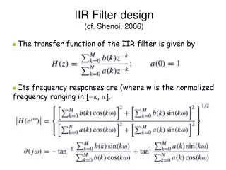
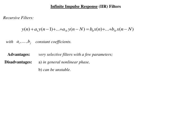
Infinite Impulse Response (IIR) Filters. Recursive Filters:. with constant coefficients. Advantages: very selective filters with a few parameters; Disadvantages: a) in general nonlinear phase, b) can be unstable. analog. digital. s-plane. z-plane.

E N D
Infinite Impulse Response (IIR) Filters Recursive Filters: with constant coefficients. Advantages:very selective filters with a few parameters; Disadvantages: a) in general nonlinear phase, b) can be unstable.
analog digital s-plane z-plane Design Techniques:discretization of analog filters Problem: we need to map the derivative operator “s” into the time shift operator “z”, and make sure that the resulting system is still stable.
Two major techniques • Euler Approximation (easiest), • Bilinear Transformation (best). Euler Approximation of the differential operator: approximation of “s” take the z-Transform of both sides:
analog digital s-plane z-plane Example: take the analog filter with transfer function and discretize it with a sampling frequency . By Euler’s approximation The filter is implemented by the difference equation
Problem with Euler Approximation: it maps the whole stable region of the s-plane into a subset of the stable region in the z-plane s-plane z-plane since if Re[s]<0.
C B A D nT-T nT Bilinear Transformation. It is based on the relationship Take the z-Transform of both sides: which yields the bilinear transformation:
Main Property of the Bilinear Transformation: it preserves the stability regions. s-plane z-plane since:
Mapping of Frequency with the Bilinear Transformation. Magnitude: Phase: where
See the meaning of this: it is a frequency mapping between analog frequency and digital freqiency.
Example:we want to design a digital low pass filter with a bandwith and a sampling frequency . Use the Bilinear Transformation. Solution: • Step 1: specs in the digital freq. domain • Step 2: specs of the analog filter to be digitized: or equivalently • Step 3: design an analog low pass filter (more later) with a bandwith ; • Step 4: apply Bilinear Transformation to obtain desired digital filter.
Design of Analog Filters Specifications: pass band transition band stop band
Two Major Techniques: Butterworth, Chebychev Butterworth: Specify from passband, determine N from stopband:
Poles of Butterworth Filter: which yields the poles as solutions N=2 and choose the N poles in the stable region. + + poles + + s-plane
Example: design a low pass filter, Butterworth, with 3dB bandwith of 500Hz and 40dB attenuation at 1000Hz. Solution: solve for N from the expression poles at
Chebychev Filters. Based on Chebychev Polynomials: Property of Chenychev Polynomials: within the interval Chebychev polynomials have least maximum deviation from 0 compared to polynomials of the same degree and same highest order coefficient
root root root Why? Suppose there exists with smaller deviation then But: has degree 2 … … and it cannot have three roots!!! So: you cannot find a P(x) which does better (in terms of deviation from 0) then the Chebychev polynomial.
Chebychev Filter: Since (easy to show from the definition), then
Design of Chebychev Filters: Formulas are tedious to derive. Just give the results: Given: the passband, and which determines the ripple in the passband, compute the poles from the formulae s-plane
Example:design a Chebychev low pass filter with the following specs: • passband with a 1dB ripple, • stopband with attenuation of at least 40dB. Step 1: determine . The passband frequency For 1dB ripple, Step 2: determine the order N. Use the formula with , to obtain
Frequency Transformations We can design high pass, bandpass, bandstop filters from transformations of low pass filters. Low Pass to High Pass: same value at
Low Pass to Band Pass: The tranformation maps
How to make the transformation: Consider the transfer function then with we obtain with zeros and poles solutions of also n-m extra zeros at s where
IIR filter design using Matlab In Matlab there are three functions for each class of filters (Butterworth, Chebytchev1, Chebytchev2): BUTTAP CHEB1AP CHEB2AP Poles and Zeros of Analog Prototype Filter BUTTER CHEBY1 CHEBY2 Numerator and Denominator from N and BUTTORD CHEBY1ORD CHEBY2ORD N and from specifications Example. We want to design an IIR Digital Filter with the following specifications: Pass Band 0 to 4kHz, with 1dB ripple; Stop Band > 8kHz with at least 40 dB attenuation Sampling frequency 40kHz Type of Filter: Butterworth. Using Matlab: >> [N, fc]=butterord(fp, fs, Rp, Rs); % fp, fs=passband and stopband freq relative to Fs/2 >> [B, A]=butter(N, fc); % B, A vectors of numerator and denominator coefficients. In our case: [N, fc]=butterord(4/20, 8/20, 1, 40), would yield N=7, fc=0.2291; [B, A]=butter(7, 0.2291), would yield the transfer function B(z)/A(z).
Let’s verify these numbers: Step 1: specifications in the digital frequency domain: Step 2: specifications for analog filter from the transformation
Step 3: choose (say) Butterworh Filter with and from the ripple specification Step 4: determine order N from attenuation of 40dB with yields N=7
Step 5: finally the cutoff frequency, from the equation Which yields , corresponding to a digital frequency Step 6: the desired Filter is obtained by the function [num, den] = butter( 7 , 0.6889/)