Download
1 / 22
220 likes | 342 Views
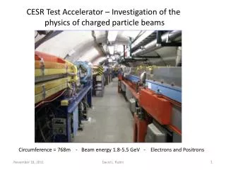
The CESR Test Accelerator and Intra-beam Scattering. David Sagan Cornell Laboratory for Accelerator-Based Sciences and Education. Outline. Introduction to the CESR Test Accelerator Motivation: ILC Damping Ring R&D Concept & planned R&D Unique features Scheduling Lattice parameters

E N D
The CESR Test Accelerator and Intra-beam Scattering David Sagan Cornell Laboratory for Accelerator-Based Sciences and Education
Outline • Introduction to the CESR Test Accelerator • Motivation: ILC Damping Ring R&D • Concept & planned R&D • Unique features • Scheduling • Lattice parameters • Bunch size measurement • IBS in CesrTA • Transverse and Longitudinal current dependencies • Energy dependence • Conclusion & Acknowledgements IBS 2007 Workshop, Darsbury
The ILC • Machine Configuration • Helical Undulator polarized e+ source • Two 6.7 km damping rings • RTML running length of linac • 11.2 km Main Linac • Single Beam Delivery System • 2 Detectors in Push-Pull Configuration • Basic Numbers • 500 GeV – upgradeable to 1 TeV • 14 kHz Collision Rate • Luminosity: 2x1034 cm-2s-1 • 31 km end-to-end length • 31.5 MV/m SRF cavities IBS 2007 Workshop, Darsbury
The ILC Damping Ring Parameters • Some high priority Damping Ring R&D Issues: • Electron Cloud Effects. • Ion effects. • Fast injection and extraction kickers • Low-emittance tuning • Impedance-driven single-bunch instabilities. IBS 2007 Workshop, Darsbury
CesrTA Concept • Mid 2008: The Cornell CESR e+/e- colliding beam storage ring will stop doing high energy physics. • CesrTA idea: Reconfigure CESR as an ILC damping ring test facility to Provide an R&D program that is complementary to work going on elsewhere (eg, KEK-ATF): • Move wigglers to zero dispersion regions for low emittance operation • Open up space for insertion devices and instrumentation • CesrTA will provide a vehicle for: • R&D needed for EDR decisions • Operating and tuning experience with ultra-low emittance beams • Damping Ring technical systems development IBS 2007 Workshop, Darsbury
Ring Modifications for CesrTA • Place all wigglers in zero dispersion regions • Vacuum system modifications • Remove 4 of 6 electrostatic separators • Upgrade instrumentation and diagnostics • Feedback system modifications for 4 ns bunch spacing • Basic ring modifications will take place in a single 3 month down period (mid 2008) IBS 2007 Workshop, Darsbury
ILC DR R&D Issues and CesrTA • Some R&D Items that Can Be Addressed at CesrTA: • Electron Cloud • Growth in quadrupoles, dipoles, and wigglers • Suppression in quadrupoles, dipoles, and wigglers • Instability thresholds and emittance growth in the positron damping ring • Ion Effects • Instability thresholds and emittance growth in the electron damping ring • Ultra-low Emittance Operation • Alignment and Survey • Beam-based Alignment • Optics Correction • Measurement and Tuning • Fast (single bunch) high voltage kickers for injection/extraction • >100 kV-m of stripline kick required • <6 ns wide pulse into a 0.3 m long stripline so as not to perturb neighboring bunches in the damping ring • Test and Demonstrate Key Damping Ring Technologies • Wiggler vacuum chambers, optimized wigglers, diagnostics, etc… IBS 2007 Workshop, Darsbury
Unique R&D Featuresof CESR • CESR offers: • The only operating wiggler-dominated storage ring in the world (90%) • The CESR-c damping wigglers • Technology choice for the ILC DR baseline design • Physical aperture: Acceptance for the injected positron beam • Field quality: Critical for providing sufficient dynamic aperture in the damping rings • Flexible operation with both positrons and electrons • The ability to operate with positrons and with the CESR-c damping wigglers offers a unique experimental reach • Flexible bunch spacings suitable for damping ring tests • Presently operate with 14 ns spacing • Can operate down to 4ns (or 2ns) spacings with suitable feedback system upgrades • Flexible energy range from 1.5 to 5.5 GeV • CESR-c wigglers and vacuum chamber specified for 1.5-2.5 GeV operation • An ILC DR prototype wiggler and vacuum chamber could be run at 5 GeV IBS 2007 Workshop, Darsbury
CesrTA Operating Model • Cornell provides infrastructure, operations staff, and support • Experimental periods each year with alternate running periods for CHESS • International Collaboration (Letters of intent from ~30 collaborators): IBS 2007 Workshop, Darsbury
ILC Time Line • "Technology Driven" Time Line: • Feb 2007: Reference Design Report (RDR) released. • Early 2010: Engineering Design Report (EDR) due • With critical R&D completed. • 2012: Begin construction. • 2019: End construction. IBS 2007 Workshop, Darsbury
CesrTA Schedule • Initial Focus • Electron cloud growth and suppression in wigglers • Improvements for low emittance operations through 2009 • ILC EDR needs will drive research program until early 2010 • Expect re-evaluation of program at that point • Potential for prototype testing after the EDR period • At NSF request, we have resubmitted the CesrTA proposal jointly to DOE and NSF IBS 2007 Workshop, Darsbury
CesrTA Baseline Lattice Baseline Lattice IBS 2007 Workshop, Darsbury
Alternate Optics • Have explored a range of optics for physics studies: IBS 2007 Workshop, Darsbury
Instrumentation for Ultra-Low Emittance Measurement • Typical CesrTA Beam Sizes • Vertical: y~10-12 m • Horizontal: x ~ 80 m (at a zero dispersion point) • Have considered laserwire and X-ray profile monitors • Fast X-ray imaging system (Alexander) • Core diagnostic for CesrTA – high resolution and bunch-by-bunch capability • First pinhole camera tests were successful! (see next slide) • Laserwire • CESR-c fast luminosity monitor offers window suitable for laserwire use IBS 2007 Workshop, Darsbury
GaAs Detector for X-ray Imaging First bunch-by-bunch beam size data [Test setup used pinhole camera] Signal (ADC Counts) • = 142 +/- 7 mm Different symbols represent different bunches Pinhole camera setup at B1 hutch Fast enough for single bunch resolution Position (mm) • NEW: GaAs arrays from • Hamamatsu • 1x512 linear array • 25 m pitch IBS 2007 Workshop, Darsbury
zone plate detector 25um Be Multilayer W/C mirrors; q p CesrTA X-Ray Beamsize Monitor Concept • Single bunch, 1m resolution • Simple optics • High transmission • 2 keV operation (works for both 2 GeV and 5 GeV) • Hundreds (2 GeV) to thousands (5 GeV) of photons per bunch passage • Explore other detector possibilities (eg, InSb arrays) IBS 2007 Workshop, Darsbury
Nominal Values Alignment sensitivity and Low Emittance Correction Algorithms • Have evaluated our ability to correct for ring errors • Goal: y~5-10 pm at zero current • Simulation results indicate that we can reasonably expect to meet our targets IBS 2007 Workshop, Darsbury
IBS in CesrTA(Transverse Beam Size) In CesrTA the horizontal and vertical beam size is strongly current current dependent: Analysis follows procedure outlined by Andy Wolsky. Calculation using Bmad IBS 2007 Workshop, Darsbury
IBS in CesrTA(Longitudinal Beam Size) Since the horizontal beam size is dominated by the dispersion and energy spread, the longitudinal beam size is relatively weakly dependent upon the current IBS 2007 Workshop, Darsbury
IBS Energy Dependence Energy flexibility of CesrTA and -4 IBS dependence offers a flexible way to study, control and understand IBS contributions to emittance relative to other physics under consideration: IBS 2007 Workshop, Darsbury
Conclusion • CesrTA conceptual design work is ongoing • Program offers unique features for critical ILC damping ring R&D • Simulations indicate that the emittance reach of CesrTA is suitable for a range of damping ring beam dynamics studies • Offers a flexible platform for studying IBS IBS 2007 Workshop, Darsbury
Acknowledgments • CesrTA Studies and CESR Machine Studies • J. Alexander • M. Billing • G. Codner • J. Crittenden • M. Ehrlichman • M. Forster • D. Hartill • R. Helms • D. Rice • D. Rubin • D. Sagan • L. Schachter • J. Shanks (REU) • E. Tanke • M. Tigner • J. Urban IBS 2007 Workshop, Darsbury