Download
1 / 25
250 likes | 578 Views
Overview. Quick look at some common MEMS actuators Piezoelectric Thermal Magnetic Next: Electrostatic actuators Actuators and mechanism Beams. MEMS Actuation Options. Piezoelectric Thermal Magnetic Electrostatic Dynamics Beam bending Damping. Ferroelectrics (piezoelectrics).

E N D
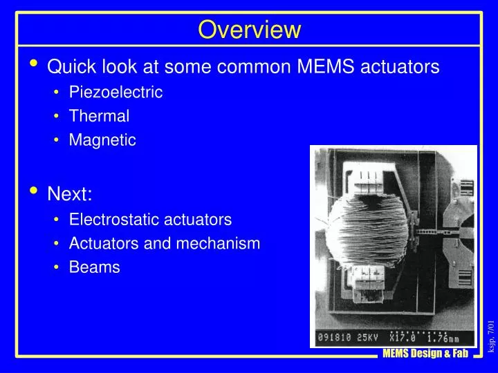
Overview • Quick look at some common MEMS actuators • Piezoelectric • Thermal • Magnetic • Next: • Electrostatic actuators • Actuators and mechanism • Beams
MEMS Actuation Options • Piezoelectric • Thermal • Magnetic • Electrostatic • Dynamics • Beam bending • Damping
Ferroelectrics (piezoelectrics) • Huge energy densities • Good efficiency • Huge force, small displacement • Major fabrications challenges • Continuously promising technology
V A L d - piezoelectric coefficient rank 2 tensor: e.g. d11, d31 Piezoelectric effect • Polyvinylidene flouride (PVDF) • Zinc oxide - ZnO • Lead zirconate titanate – PZT • PMNPT
Piezoelectric products • Quartz resonators (single crystal) • E.g. crystal oscillators • ~10Million/day, $0.10 each, vacuum packaged V A L
Bimorph for STM and AFM Aluminum electrodes ZnO After Akamine, Stanford, ~90
Piezoelectric Actuator Summary • High voltage, low current • ~100V/um • No static current (excellent insulator) • Highest energy density of any MEMS actuator but • Large force, small displacement • Typically very difficult to integrate with other materials/devices • “Continuously promising”
Thermal Expansion L A • = g DT is the thermal expansion strain (dL/L) • = E e is the thermal expansion stress F = A s is the thermal expansion force gsilicon ~ 2.3x10⁻⁶/K .
Thermal actuator worksheet • Assume that you have a silicon beam that is 100 microns long, and 1um square. You heat it by 100K. How much force do you get if you constrain it? How much elongation if you allow it to expand? TCE for silicon is 2.3x10^-6/K . Area= • = g DT = • = E e = F = A s = dL= e L=
Thermal expansion: The heatuator Plot by: R. Conant, UCB.
Thermal Actuators Uses thermal expansion for actuation Very effective and high force output per unit area Actuator translates in this direction Cold arm Current output pad Hot arm Cascaded thermal actuators for high force Current input pad
Thermal actuators in CMOS Shen, Allegretto, Hu, Robinson, U. Alberta Joule heating of beams leads to differential thermal expansion, changing the angle of the mirror
Bubble actuators (thermal and other) • Lin, Pisano, UCB, ~92? • HP switch • Papavasiliu, Pisano, UCB - electrolysis
Thermal actuator summary • Easy process integration! • Large forces, small displacements • Need lever mechanisms to trade off force for displacement • Typically very inefficient • Time constants ~1ms • Substantial conduction through air • Minimal convection in sub-millimeter designs • Radiation losses important above ~300C • Instant heating, slow cooling • Except when radiative losses dominate
Magnetic actuators • Lorentz force • Internal current in an external (fixed) magnetic field • Dipole actuators • Internal magnetic material in an external (varying) field
Magnetic Actuation (external field) • Fabrication: NiFe electroplating • Switching external field • Packaging External magnetic field NiFe electroplated on polysilicon Silicon substrate
Magnetic Parallel Assembly Parallel assembly of Hinged Microstructures Using Magnetic Actuation Yong Yi and Chang Liu Microelectronics Laboratory University of Illinois at Urbana-Champaign Urbana, IL 61801 Figure 1. (a) An SEM micrograph of a Type I structure. The flap is allowed to rotate about the Y- axis. (b) Schematic cross-sectional view of the structure at rest; (c) schematic cross-sectional view of the flap as Hext is increased. Figure 2. (a) SEM micrograph of a Type II structure. (b) Schematic cross-sectional view of the structure at rest; (c) schematic cross-sectional view of the structure when Hext is increased. Solid-State Sensor and Actuator Workshop Hilton Head 1998
Parallel assembly Parallel assembly of Hinged Microstructures Using Magnetic Actuation Yong Yi and Chang Liu Microelectronics Laboratory University of Illinois at Urbana-Champaign Urbana, IL 61801 Figure 8. Schematic of the assembly process for the flap 3-D devices. (a) Both flaps in the resting position; (b) primary flap raised to 90º at Hext = H1; (c) full 3-D assembly is achieved atHext = H2 (H2 > H1 ). Figure 9. An SEM micrograph of a 3-D device using three Type I flaps. The sequence of actuation is not critical to the assembly of this device. Solid-State Sensor and Actuator Workshop Hilton Head 1998
Magnetic actuators – Onix switch? • Magnetic actuation, electrostatic hold
Magnetic actuators in CMOS Resonant Magnetometer B. Eyre, Pister, Judy Lorentz force excitation Piezoresistive detection
LIGA: synchrotron lithography, electroplated metal Closed Loop Controlled, Large Throw, Magnetic Linear Microactuator with 1000 mm Structural Height H. Guckel, K. Fischer, and E. Stiers U. Wisconsin Micro Electro Mechanical Systems Jan., 1998 Heidelberg, Germany
Magnetic Actuation in LIGA U. Wisconsin Micro Electro Mechanical Systems Jan., 1998 Heidelberg, Germany
Magnetic Actuation in LIGA U. Wisconsin Micro Electro Mechanical Systems Jan., 1998 Heidelberg, Germany
Magnetic actuator summary • High current, low voltage (contrast w/ electrostatics) • Typically low efficiency • Potentially large forces and large displacements • Some process integration issues