Download
1 / 12
260 likes | 649 Views
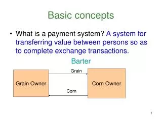
Basic FEA Concepts. FEA Project Outline. START. Finite Element Analysis. 1. 2. 3. 4a. Consider the physics of the situation. Devise a mathematical model. Obtain approximate results for subsequent comparison with FEA. Plan a finite element discretization of the mathematical model.

E N D
FEA Project Outline START Finite Element Analysis 1 2 3 4a Consider the physics of the situation. Devise a mathematical model. Obtain approximate results for subsequent comparison with FEA. Plan a finite element discretization of the mathematical model. Preprocess: Build the finite element model in the computer. D2 D1 4b Physics FEA H Revise the finite element discretization Are error estimates small? Does mesh revision do little to alter the FEA results? Solution: Generate and solve equations of the finite element model. No What is at fault, Inadequate physical basis for the model or a poor finite element model? Yes STOP 4c No 5 Postprocess: Output/display computed results for examination. Yes Are the FEA results free of obvious errors, such as disagreement with the intended boundary conditions? Are FEA results physically reasonable? Do FEA results agree reasonably well with predictions and approximations obtained by other means? Adapted from RD Cook et al., Concepts and Applications of Finite Element Analysis, 4th ed., John Wiley & Sons, 2002
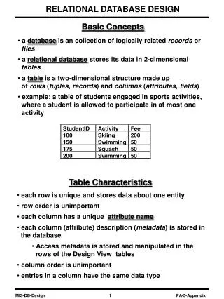
Mechanics Analysis • Geometry • Boundary Conditions • Constitutive Relationships • These basic elements the same whether the analysis is “engineering”, theory of elasticity, continuum mechanics, or finite element analysis • The approachable problems are very different, with FEA being the most general (but not necessarily the best)
Geometry • Defines the spatial region over which the field quantities are defined • Defines the boundaries where surface tractions (constraints and loads) are specified • All problems are 3D, but certain problems lend themselves to 2D or even 1D approaches • Important FEA points: • An “element” is much more than a geometric entity • More geometric detail is not necessarily better
Boundary Conditions • Points or surfaces where constraints are specified or loads are applied • Constraints are often displacement = known value points • Loads are generally point forces or pressures • Boundary conditions are also used to enforce symmetry in reduced geometry problems (e.g. half, quarter models) • Important FEA points: • Rigid body motions must be prevented by the constraints • It is very easy to over/under constrain a model • Pressures end up being point (node) loads, check carefully
Constitutive Relationships • The sophisticated term for “material properties” • This is generally the most difficult and troublesome part of advanced simulations • Think more broadly than isotropic linear elasticity • Anisotropy is common (e.g. fiber composite materials) • Plasticity is common (what happens after yield?) • Damage and Fracture are common • Important FEA points: • Many constitutive models are available • Just because it runs, doesn’t mean it’s right
Our Introductory Problem • Cross-sectional area: • A = 400 mm2 • Modulus of Elasticity: • E = 200 GPa • Poisson’s Ratio: • n = 0.32 • We are interested in: • Stresses in the truss members • Deflections at the load points
Getting Started • Just mechanics going on here. Linear elasticity for now. No friction. Small deflections. • You have some work to do here: • Statics analysis to determine reaction forces and internal member forces • Simple F/A calculation for the dominant stress component • Castigliano’s approach to determine the deflections (this takes some work) • We need to consult our Element Library for this step • Is this a 3D, 2D, or 1D problem? • Are there any sub-components, and are they 3D, 2D, or 1D? • What is the fundamental behavior of the sub-components? 1 2 3 Consider the physics of the situation. Devise a mathematical model. Obtain approximate results for subsequent comparison with FEA. Plan a finite element discretization of the mathematical model.
Approximate Results FABY FABX q FAG RAy RAy F1 F2 REy Stay organized, use symmetry …
Castigliano’s Theorem For a truss, Castigliano’s Theorem becomes: To determine the partial derivatives, you must express the member forces as functions of the truss loads …
Element Libraries • Commercial Finite Element Codes have extensive element collections (marc_2010_doc_volume_b.pdf) • Marc, as of today, has 227 elements in the library • Structural elements have 1D, 2D, and 3D geometry • Geometry is not the only important consideration!
Truss Element • Review Element 9 in the library • This is the truss element introduced in ME 420/520 • It is 1D in geometry, thus we will have an element property required (cross-sectional area) • It allows no variation of element or material properties along the element length • This element does not have any bending stiffness • It can be mixed together with other elements of different materials or properties in the same truss