Download
1 / 14
140 likes | 387 Views
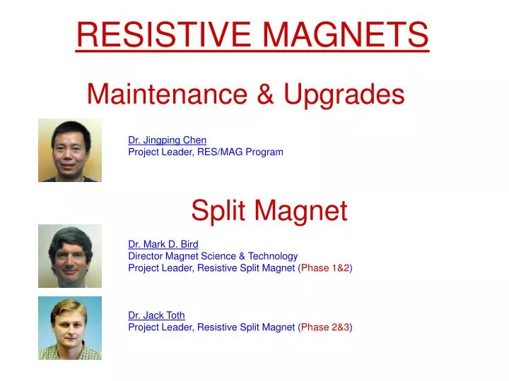
RESISTIVE MAGNETS. Maintenance & Upgrades. Dr. Jingping Chen Project Leader, RES/MAG Program. Split Magnet. Dr. Mark D. Bird Director Magnet Science & Technology Project Leader, Resistive Split Magnet ( Phase 1&2 ). Dr. Jack Toth Project Leader, Resistive Split Magnet ( Phase 2&3 ).

E N D
RESISTIVE MAGNETS Maintenance & Upgrades Dr. Jingping Chen Project Leader, RES/MAG Program Split Magnet Dr. Mark D. Bird Director Magnet Science & Technology Project Leader, Resistive Split Magnet (Phase 1&2) Dr. Jack Toth Project Leader, Resistive Split Magnet (Phase 2&3)
Resistive Magnet Cells: Presently & Planned Cell 2 SPLIT 2010 Cell 4 LB 195mm 19.5 T Cell 6 Keck 12ppm 52mm 25T Cell 8 35T 32mm Cell10 Cell12 33T 32mm 35T ~2010 Cell14 SCH36T 2012 Cell16 Cell 1 Cell 3 Cell 5 50mm 31T Cell 7 50ppm 32mm 28T Cell 9 32 mm to 50 mm31T Oct 2008 Cell11 Cell13 Test Stand I Test Stand II Cell15 Hybrid 45T 3 PS J. Chen, S. Gundlach, R.F. Stanton, J. Toth, J. O Reilly, C. Ray Presently: 7 Resistive Magnets incl. 1 Upgrade & 1 Hybrid (3 PS) Planned:1 Upgrade, 1 Series-Connected Hybrid and a Split Magnet Maintenance past year 14 coils stacked, 9 coils installed, Spares available for all magnets. Jim O’Reilly: Project Leader, RES/MAG Maintenance Jingping Chen: Project Leader, RES/MAG Program
SPLIT RESISTIVE MAGNET Project Leader: Jack Toth Scott Bole, Scott Gundlach, M. D. Bird, J. O’Reilly • I) USER INTERFACE • * Cell Layout: Scattering & Rotation Configuration • * Sample Space (Ports and Bore) • * Magnetic Field (NHMFL Split vs. existing Split Magnets) • MAGNET TECHNOLOGY • * ‘The Wheel’: Separating Vacuum from 32bar water pressure • * Hydraulics: How to get +200 l/s water through the midplane • * Magnet Winding: Florida Helix & Preliminary Coil Design • SCHEDULE • * Completed Milestones (Phase 1 & 2) • * Plan for Scattering User Magnet (Phase 3)
User Interface: Preliminary Cell Layout Dewar 32mm bore Scattering Configuration Cooling water pipes small table: 4’ x 8’ split magnet housing >25T 45° 45° big table: 5’ x 10’ >25T 11.4° 4 x scattering cone (line of sight) aligned with cell vs. 45° 4 tapered access ports each: 11.4° x 45° ~ 1m
User Interface: Preliminary Cell Layout Rotation Configuration small table: 4’ x 8’ Cooling water pipes split magnet housing 32mm 32mm 32mm Dewar 32mm bore big table: 5’ x 10’ >24T large, straight access ports perpendicular AND parallel to magnetic field each: 32mm >24T
User Interface: Vacuum=Sample Space Scattering Configuration 4 tapered ports: 11.4°x 45°off 5mm sample Scattering possible at any angle! B>25T >25T 2 x 5.7° (f5) take-off angle V= 11.4° ports >24T 32mm bore 5mm sample diameter 32mm bore d=32mm H=45° 4 large straight ports each: d=32mm , B>24T d=32mm H=45° H=45° Rotation Configuration H=45°
10 MW SCH 40 MW 20 MW Grenoble 16 MW MIT User Interface: Magnetic Field NHMFL: scattering ** >25T & 28MW NHMFL: rotation** >24T & <28MW **: >25 T applies for scattering configuration (5 coils), Re-using same outer coils (C&D) delivers >24 T for new rotation insert (coil A1&A2&B)both consuming <28MW (leaving voltage margins)
Magnet Technology: Wheel=Vacuum Barrier outside: 40 bar water “Wheel”: * Stainless Steel Structure (special part of housing=conical ports) * Separating vacuum from 40bar water pressure Optimization Goal: * minimum (tapered) wall thicknesses while * maintaining reasonable compliance (limit max. deflections) and * keeping stresses within ASME BPVC allowables inside: vacuum COMPLIANCE=deflections (magnified) STRESS INTENSITY (TRESCA) Membrane < 138 MPa / Mem+Bending < 207 MPa Peak Stress: max S=287 MPa < 345 MPa max u(sum)~0.1mm FEA: user magnet / version# wheel_01_005 / geometry #06 / date: 11/03/2008
Magnet Technology: Hydraulics around the ports Mid-plane region must include space for cooling water (total~220 l/s) Optimization Goal: minimum water gaps while limiting water velocities (max<20m/s) and pressure drop (total dp<25bar) Hydraulics: model coil / version# wma_109 / date: 04/13/2006 (design review)
Magnet Technology: Split Florida-Helix Split Florida Helix (A1/A2) must include cooling holes (25/50 l/s), tie rods or alignment rods, support current (13/27 kA), provide structural support for coil clamping (33/178 kN) WHILE maintaining a stable coil pack (with fixed insulation) considering assembly/maintenance plan. I) Developed new Split Florida-Helix technology (NHMFL Proprietary, Pat. Pend.) & manufactured prototype. II) Developed 3-D FEA Model plus in-house code (including torque and non-symmetric clamping with frictional contact). FEA: model coil / version# FLhelix3d_wma111F_006 / date: 09/18/2006
Schedule: Completed Milestones Phase 1: Conceptual Design COMPLETED 2Q’05 ON SCHEDULE * Hybrid vs. Resistive* 4 elliptical ports, v=11.4° x h=45° * Radial vs. Axial Cooling * Poly-Helix vs. Florida-Bitter • Phase 2: Model Coils (WMA I+II) • COMPLETED Aug’08 ON SCHEDULE * Manufactured prototype of Split Florida Helix * Demonstrated & successfully tested new technology in 20T LB 5 cycles to 32T and 20 cycles to 31T w/o degradation • Phase 3: Scattering User Magnet • RESUMED OCT ’08 • * Await Funds: 1Q’08-3Q’08 • * General Coil Design: 4Q’08