Download
1 / 58
800 likes | 1.44k Views
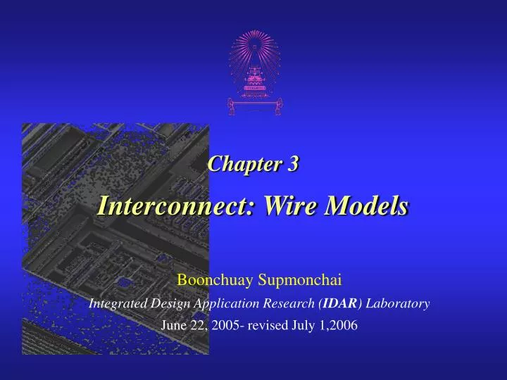
Chapter 3 Interconnect: Wire Models. Boonchuay Supmonchai Integrated Design Application Research ( IDAR ) Laboratory June 22, 2005- revised July 1,2006. Outlines. Interconnects at first glance Wire Capacitances Wire Resistances Wiring Models Wire Inductance. Transmitters. Receivers.

E N D
Chapter 3Interconnect: Wire Models Boonchuay Supmonchai Integrated Design Application Research (IDAR) Laboratory June 22, 2005- revised July 1,2006
Outlines • Interconnects at first glance • Wire Capacitances • Wire Resistances • Wiring Models • Wire Inductance Interconnect: Wire Models
Transmitters Receivers Schematics Physical Interconnect: The Wire Interconnect: Wire Models
All-inclusive model Capacitance-only (R, L, and C present) Interconnect (Wire) Models Interconnect: Wire Models
State-of-the-art processes offer multiple layers of aluminum or copper, and at least one layer of polysilicon Even the n+ and p+ diffusion layers can be used for wiring purposes. Modern Interconnect Interconnect: Wire Models
Interconnect Impact on Chip Interconnect: Wire Models
Example: Intel 0.25 micron Process 5 metal layers Ti/Al - Cu/Ti/TiN Polysilicon dielectric Interconnect: Wire Models
Local Interconnect Source: Intel Global Interconnect S = S Local Technology S = S Global Die Nature of Interconnect Interconnect: Wire Models
Interconnect Parasitics • Effects of Interconnect parasitics • reduce reliability • affect performance and power consumption • Classes of parasitics • Capacitive • Resistive • Inductive Interconnect: Wire Models
Parasitic Simplifications • Inductive effects can be ignored if • The resistance of the wire is substantial enough (as is the case for long Al wires with small cross section) • The rise and fall times of the applied signals are slow enough • When the wire is short, or the cross-section is large, or the interconnect material has low resistivity, a capacitance only model can be used Interconnect: Wire Models
Parasitics Simplifications (Cont.) • When the separation between neighboring wires is large, or when the wires run together for only a short distance, interwire capacitance can be ignored and all the parasitic capacitance can be modeled as capacitance to ground Interconnect: Wire Models
Fanout Example: A Simple Wire Model Interconnect: Wire Models
Outlines • Interconnects at first glance • Wire Capacitances • Wire Resistances • Wiring Models • Wire Inductance Interconnect: Wire Models
Wiring Capacitance • The wiring capacitance depends upon the length and width of the connecting wires and is a function of the fan-out from the driving gate and the number of fan-out gates. • Wiring capacitance is growing in importance with the scaling of technology. • There are 3 components in wiring capacitance • Parallel Plate Capacitance • Fringing Capacitance • Interwire Capacitance Interconnect: Wire Models
Current Flow L W H tD Dielectric Electric Field Substrate Capacitance: The Parallel Plate Model di= Dielectric permittivity constant (SiO2= 3.9) Interconnect: Wire Models
(Relative) Permittivity of Some Materials Interconnect: Wire Models
W L W-H/2 H H First Approximate Model H W-H/2 + Second Approximate Model (per length Capacitance) Fringing Capacitance Interconnect: Wire Models
For SiO2 with relative permittivity = 3.9 Fringing versus Parallel Plate • For larger values of W/H (smaller values of H/tdi) the total capacitance approaches the parallel-plate model. • Total capacitance levels off to a constant value of approx. 1 pF/cm for line widths smaller than the insulator thickness (i.e., is no longer a function of the width) Interconnect: Wire Models
fringing parallel Interwire Interwire Capacitance Interwire capacitance is responsible for Cross-Talk Interconnect: Wire Models
For SiO2 with relative permittivity = 3.9 Impact of Interwire Capacitance • When W < 1.75H interwire capacitance starts to dominate • Interwire capacitance is more pronounced for wires in the higher interconnect layers (further from the substrate) • Wire delay nearly proportional to L2 Interconnect: Wire Models
PP in aF/m2 fringe in aF/m Wiring Capacitances (0.25 µm CMOS) per unit wire length in aF/m for minimally-spaced wires Interconnect: Wire Models
Examples of Wire Capacitances • Consider a wire of 10 cm long and 1 micron wide routed in Al1 (e.g., clock line) (over field) then • Cpp = (0.1 x 10⁶ micron2) x 30 aF/micron2 = 3 pF • Cfringe= 2 x (0.1 x 106 micron) x 40 aF/micron = 8 pF • Now, if a second wire is routed alongside the first wire with minimum separation • Cinterwire= (0.1 x 10⁶ micron) x 95 aF/micron = 9.5 pF • The same wire, if it were routed in Al4 (over field), • Cpp = 0.65 pF, Cfringe = 2.8 pF, Cinterwire = 8.5 pF Interconnect: Wire Models
Dealing with Capacitances • Use ofLow Capacitance (low-k) dielectrics (insulators) such as polymide or even air instead of SiO2 • Family of materials that are low-k dielectrics must be suitable thermally and mechanically • Must also be compatible with (copper) interconnect • Copper interconnect allows wires to be thinner without increasing their resistance, thereby decreasing interwire capacitance Interconnect: Wire Models
Dealing with Capacitances (Cont.) • Use SOI (silicon on insulator) to reduce junction capacitance • Rules of thumb! • Never run wires in diffusion • Use poly only for short runs • Shorter wires – lower R and C • Thinner wires – lower C but higher R Interconnect: Wire Models
Outlines • Interconnects at first glance • Wire Capacitances • Wire Resistances • Wiring Models • Wire Inductance Interconnect: Wire Models
L L R = = A H W L Sheet Resistance R H W R1 = R2 Wire Resistance Resistance of a square conductor is independent of its absolute size Interconnect: Wire Models
Interconnect Resistance • Aluminum used due to low cost and compatibility with fab process • Top of the line processes (e.g., IBM) are now increasingly using Copper as the conductor of choice Sheet Resistance for a typical 0.25 micron CMOS process Resistivity of commonly used conductor (at 20 C) Interconnect: Wire Models
W • = (/(f)) where f is frequency = 4 x 10⁻⁷ H/m H Skin Effect • At high frequency, currents tend to flow primarily on the surface of a conductor with the current density falling off exponentially with depth into the wire • = 2.6 m for Al at 1 GHz so the overall cross section is ~ 2(W+H) Example: H = 10 and W = 20, at 1 GHz effective cross section area is not 200 but 2(10+20)2.6 = 156 Interconnect: Wire Models
Skin Effect (Cont.) • The onset of skin effect is at fswhere the skin depth is equal to half the largest dimension of the wire. fs = 4 / ( (max(W, H))2) where is the permeability of the surrounding dielectric • Below fs, the whole wire is conducting current • Skin effect increases resistance of the wire due to the decreased effective cross section area. Interconnect: Wire Models
for H = .70 um 1000 100 10 % Increase in Resistance 1 W = 1 um W = 10 um W = 20 um 0.1 1E8 1E9 1E10 Frequency (Hz) Skin Effect for Different W’s A 30% increase in resistance is observed for 20 m Al wires at 1 GHz (versus only a 1% increase for 1 m wires) Interconnect: Wire Models
Dealing with Resistance • Selective Technology Scaling • Scale W while holding H constant • Use Better Interconnect Materials • Lower resistivity materials like copper • Silicides (WSi2, TiSi2, PtSi2 and TaSi) • Conductivity is 8-10 times better than poly alone • More Interconnect Layers • Reduce average wire-length (but beware of extra contact!) Interconnect: Wire Models
Silicide PolySilicon SiO2 + + n n p Polycide Gate MOSFET A silicide is a compound material formed using silicon and a refractory metal (W, Ti2, Pt2and Ta) to create a highly conductive material that can withstand high-temperature process steps without melting. Interconnect: Wire Models
Outlines • Interconnects at first glance • Wire Capacitances • Wire Resistances • Wiring Models • Wire Inductance Interconnect: Wire Models
Electrical Wire Models • Parasitics of the interconnect have an impact on the behavior of the circuit: delay, power dissipation, andreliability • To study these effects, electrical wire models are introduced to simulate the real behavior of the wire as a function of its parameters. • From simple to complex models are: • Ideal Wire Model • Lumped C Model • Lumped RC Model • Distributed RC Model Interconnect: Wire Models
Ideal Wire Model • Wires are treated as simple lines with no attached parameters or parasitics • Same voltage is present at every segment of the wire at every point in time - at equi-potential • Voltage change at one end propagates immediately to the other ends, no matter how far, without delay. • Only holds for very short wires, i.e., interconnects between very nearest neighbor gates • Small circuit components: gates Interconnect: Wire Models
Lumped Model • Different fractions (distributed parasitics) can be lumped into a single circuit element, if • Only a single parasitic component (R, C, or L) is dominant • The interaction between the components is small • Only one aspect of the circuit behavior is the focus • Advantage: Effects of parasitics can be described by an ordinary differential equation • Distributed Model requires Partial Differential Eq. Interconnect: Wire Models
Lumped C Model • When the resistive component is small and the switching frequency is low to medium, only capacitive component of the wire can be considered and lumped into a single C Still equipotential! • Simple yet effective; only introduces the loading effect of the capacitor onto the driving gate Interconnect: Wire Models
driver Rw Rdriver wire Vin Vout Cw Lumped RC model • Total wire resistance is lumped into a single R and total capacitance into a single C • Good for short wires; pessimistic and inaccurate for long wires Interconnect: Wire Models
(r,c,L) Vin VN rL rL rL rL rL Vin VN cL cL cL cL cL Diffusion Equation (N ) Distributed RC model • Circuit parasitics are distributed along the length, L, of the wire • c and r are the capacitance and resistance per unit length Interconnect: Wire Models
RC Tree Characteristics What is a RC Tree? A RC Network is a Tree if … • A unique resistive path exists between the source node and any node of the network • Single input (source) node, s • All capacitors are between a node and GND • No resistive loops Interconnect: Wire Models
RC Tree Elmore Delay • Solving for Delay time at any points in the tree is intractable. • Exact Analyses involve solving differential equations of very high degree. • Every Capacitor added raises the degree of the differential equations by one. • Elmore Delay Calculation is a reasonable approximation to the exact solution. • Beware of the Tree assumption! • Once again, good for short wires and give pessimistic results. Interconnect: Wire Models
RC Tree Elmore Delay (Cont.) • Path resistance sum of the resistances on the path from the input node to node i Rii = Rj (Rj [path(s i)]) • Shared path resistance resistance shared along the paths from the input node to nodes i and k Rik = Rj (Rj[path(s i) path(s k)]) • Elmore Delay at node i in an RC tree is given by first-order time constant of the network Interconnect: Wire Models
Example: Elmore Delay Calculation • Find the Delay (after input dropped) at terminal 4. Interconnect: Wire Models
1 = C1R1 2 = C1R1 +C2(R1+R2) R1 R2 Ri-1 Ri RN 1 2 i-1 i N VN Vin C1 C2 Ci-1 Ci CN i = C1R1+C2(R1+R2)+…+Ci(R1+R2+…+Ri) Elmore delayequation RC Chain Elmore Delay i= N(N+1)RC/2 If all Ri are equal and all Ci are equal then Interconnect: Wire Models
A Simple Distributed RC Wire Model • An RC wire of length L can be modeled by N segments of equal length L/N • Givenr and c, the wire resistance and wire capacitance per unit length • The resistance and capacitance of each segment are given by r L/N and c L/N • From the RC chain Elmore delay, Interconnect: Wire Models
Distributed RC Model Approximation • For large number of segments N In terms of distributed parameter • Observation: • Delay of a wire is a quadratic function of its length, L • The delay is only half of that predicted by the lumped RC model Interconnect: Wire Models
1 0 Step Responses of RC Wire Models L = 1 Needs to solve a set of partial differential equations Vi Vo Interconnect: Wire Models
- Accuracy + Other Distributed Lumped Models Distributed π Model Distributed T Model Interconnect: Wire Models
Step Response Examples • Consider a Al1 wire 10 cm long and 1 m wide • Using a lumped C only model with a source resistance (RDriver) of 10 k and a total lumped capacitance (Clumped) of 11 pF • tp = 0.69 x 10 k x 11pF = 76 ns • tr = 2.2 x 10 k x 11pF = 242 ns • Using a distributed RC model with c = 110 aF/m and r = 0.075 /m • tp = 0.38 x (0.075 /m) x (110 aF/m) x (105m)2 = 31.4 ns • tr = 0.9 x (0.075 /m) x (110 aF/m) x (105m)2 = 74.25 ns • Poly: tr = 0.38 x (150 /m) x (88+254 aF/m) x (105m)2 = 112 s • Al5: tr = 0.38 x (0.0375 /m) x (5.2+212 aF/m) x (105m)2 = 4.2 ns Interconnect: Wire Models
Total Delay Propagation Delay Putting It All Together • The delay introduced by wire resistance becomes dominant when (RwCw)/2 ≥ RsCw(when L ≥ 2Rs/rw) • For an Rs = 1 kΩ driving a 1 µm-wide Al1 wire, Lcritis 2.67 cm Interconnect: Wire Models