Download
1 / 12
120 likes | 155 Views
7-3--Unipolar Signaling vs. Bipolar Signaling. 50 W. 50 W. Kn=25%. ±30mV. +. 50 W. I1(±15%). 50 W. -. I1/2(±15%).

E N D
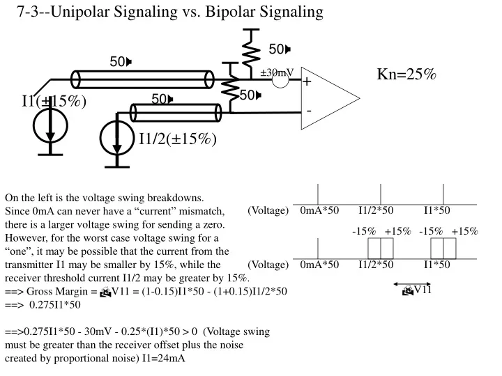
7-3--Unipolar Signaling vs. Bipolar Signaling 50W 50W Kn=25% ±30mV + 50W I1(±15%) 50W - I1/2(±15%) On the left is the voltage swing breakdowns.Since 0mA can never have a “current” mismatch,there is a larger voltage swing for sending a zero.However, for the worst case voltage swing for a “one”, it may be possible that the current from the transmitter I1 may be smaller by 15%, while the receiver threshold current I1/2 may be greater by 15%. ==> Gross Margin = V11 = (1-0.15)I1*50 - (1+0.15)I1/2*50 ==> 0.275I1*50 ==>0.275I1*50 - 30mV - 0.25*(I1)*50 > 0 (Voltage swing must be greater than the receiver offset plus the noise created by proportional noise) I1=24mA (Voltage) 0mA*50 I1/2*50 I1*50 -15% +15% -15% +15% (Voltage) 0mA*50 I1/2*50 I1*50 V11
The previous solution assumed that the proportional voltage swing on the line was just I1. Actually, the worst case wouldbe if the agressor had 1.15I1 current for its voltage swing, while this particular line had the worst case voltage swing(0.85I1).In this case, 0.275I1*50 - 30mV - 0.25*(1.15*I1)*50 > 0 In this situation, you will never get this signaling scheme to work, since the lefthand side will never be greater than zero. Another possibility for this unipolar problem is to slightly reduce the reference I1/2, so that we can convert the asymmetric “1” and “0” symbols to have equal noies margins. In that case, we have, V00 = V11 C*I1(0.85) = (0.85)* I1 - C*I1*(1.15) 2 2 ==> V00 = 0.361* I1 0.361*I1*50 - 30mV - 0.25*I1*50 > 0 ==> I1 = 5.4mA Again, you could have slightly different answers if you assumed the proportional noise of 25% is multiplied by 1.15*I1 as opposed to just I1. -15% +15% -15% +15% (Voltage) 0mA*50 I1/2*50 I1*50 V00 V11 -15% +15% 0.85I1/2*50 V00 V11
Bipolar Signaling I1(±15%) 50W 50W Kn=25% ±30mV + - I1(±15%) In this situation, the middle threshold is based solely upon the receiver itself. Basically, we look at the what is the worst case voltage swings for symbols “0” and “1”. Now we have a symmetric noise margin for both a “0” and a “1”. Using our previous analysis, we have, (Voltage) 0mA*50 I1/2*50 I1*50 -15% +15% -15% +15% V11 Notice that for the proportional noise voltage swing, we used 0.25*2*I1. This is because the voltage swing really is 2*I1, and not just I1. There is no such symbol as sending zero current, and so you MUST have 2*I1 always switching. So, this 2*I1 is the voltage swing. Again, you mileage may vary is you assume the worst case voltage swing of 2*1.15*I1. ==> Gross Margin = V11 = (1-0.15)I1*50 ==> 0.85I1*50 0.85I1*50 - 30mV - 0.25*(2*I1)*50 > 0. ==> I1 = 1.71mA
Problem 3 5mA V0 50W Source Termination Krx=10%2 Agressors 0.8 Attenuation 50W ±5mV + 50W(20%) - 5mA First, let’s figure out how our crosstalk will affect our signaling system. Suppose we inject an incident voltage of 1V into a transmission line. The signal will be attenuated to 80% of its original height. 0.8V 1V This is because of the loss in the line at high frequencies(i.e. Skin effect, dielectric absorbtion). So, when we look at the proportional noise, effectively Vswing=0.8, as opposed to the full incident wave. However, our eye width actually is even smaller ==> A=0.8 2A-1 1 A First, let’s assume that the resistor is matched to the line. Then, the incident voltage V0=10mA*50/2= 250mV. However, when this voltage reaches the far end(receiver), it will get doubled to 500mV, due to the open circuit. However, due to the lossiness of the line, the real Vswing=0.8*500mV=400mV. Our receiver eye opening will be (2A-1)*500mV=300mV. ==> Our gross margin will be 300mV/2= 150mV.
The fixed offset is 5mV, so there should be no surprises here. The proportional noise is a little bit complicated. First, the termination mismatch will cause a reflection coefficient of 20%/2 = 10%. (eq. 6-22) Second, let’s look at the crosstalk. Reflected Wave V11, due to open impedance V0 V0 Incident Wave V1 V3 Z0=50, Td NEXT V2, due toreflected Wave V11 50, Td RS=40 V33 V44 (B) (A) You get 10% crosstalk onto the victim line, because when the incident wave V1 hits to receive side,it sees an open circuit and is bounced back to the transmitter, with no loss in magnitude. This basically couples 10% into the victim, in the form of NEXT V2. Notice, that the magnitude of this NEXT will be reduced by 80% of V0 at the open termination, and will be attenuated by 80%*80%*80%=0.512 at the end of the NEXT V2. We will ignore this minor point, as it is not the worst case noise. Basically, from NEXT created at the receiver end, we get 10% proportional noise. We need to multiply this by 2, as there is one agressor on both sides of the victim. 0.8*V0 0.512*V0 2*Td This point of V2 will travel 3Td--once is the incident wave, the other 2Td is the NEXT flight time
Along with part (A), we must also consider what happens to the NEXT at the transmitter end when the termination doesn’t match. Basically, the incident wave V0 will couple NEXT V3 back into the source termination. Normally, if the termination is perfectly matched to the line, you will not see this NEXT V3 at the receiver. However, we have an impedance discontinuity, and we will see NEXT bounce from the mismatch termination and now find its way going down to the receiver end. Kr = Rs - Z0 = 40-50 = -1/9 Rs+Z0 40+50 V3 0.1*V0 0.64*0.1*V0 2*Td V33 2*Td -0.64*0.1*0.111*V0 -0.1*0.111*V0 V44 2*Td -0.512*0.1*0.111*V0 -0.8*0.1*0.111*V0 Ignoring the minor components above, and assuming the worst case conditions, we will get NEXT%*Kr(source) = 10%*-0.111= -1% NEXT seen at the receiver end. (Again, this 1% proportional noise will be multiplied by 0.8*V0, due to the attenuation) Total proportional noise will therefore be: ==> 2*[Kr(mismatch)+Kr(NEXT,receiver)+Kr(NEXT,source mismatch)] = 2*[0.1+0.1+0.01]=22%
Source Termination Only Notice that we assumed the incident voltage onto the line was 250mV. Actually, if our termination is mismatched at the source, our incident voltage will not be 250mV. Instead, it will be current divided. Assuming the worst case situation, the termination resistor could be 40 Ohms, meaning the incident wave 40 * 50 *10mA=222mV. 40+50 This just reduces everything by this small amount. Extra credit will be given for assuming the incident wave is 222mV.
5mA V0 50W Receiver Termination Krx=10%2 Agressors 0.8 Attenuation 50W ±5mV + - 50W(20%) 5mA In this situation, we have receiver termination instead of transmitter termination. Now, our incident wave V0 = 10mA*50 Ohms = 500mV. There is no current division here. However, we don’t see any doubling at the receiver, since the termination is matched. So, effectively, the receiver eye opening is equivalent between parts (a) and (b)! Again, assuming 0.8 attenuation, the voltage swing seen at the receiver will be 0.8*500mV=400mV. And again, due to attenuation, the receiver eye ==> (2A-1)*500mV=300mV, leading to a gross margin=150mV. Again, this analysis doesn’t take into consideration that the 50 ohm receiver resistor is matched to the tranmission line impedance. If instead of 50 Ohms the receiver resistor is 40Ohms, then we will see more reduction of our signal swing. I.e. Instead of 500mV Vswing, we see (1-1/9)*500mV=444mV. You will obtain extra credit if you assume a different incident reflection.
The fixed offset is 5mV, so there should be no surprises here, like before. V4 V0 V3 Rs=40 V1 V11 50, Td 50, Td (A) (A) V44 In (A), the incident wave V0 couples 10% NEXT V1 back into the source. However, since the source isn’t terminated, the reflected NEXT V11 will bounce back from V1. So you will see 10% NEXT at the receiver side. It will be attenuated by 0.8, so you must multiply the 10% NEXT by the swing of 400mV to get the proportional noise. Again, all the analysis from the previous option(source termination) are also present here.(i.e. Attenuation of the crosstalk) In (B), the wave seen as V3 should get absorbed into V3. However, if Rs=40, then there will be some reflected wave V4=-1/9*V3. This will couple NEXT V44 that will be seen in the receiver. Again, this analysis is entirely similar to the previous example, and you will get -0.111*0.1= -1% crosstalk V44 seen at the receiver. Therefore, the total proportional noise will be 2[10%+1%]+10% =32%. This is exactly the same result as if we had only source termination only.
Doubly Terminated 5mA V0 V00 50W ±5mV + 50W(20%) 50W(20%) - 5mA Our final option is if we terminate both at the receiver and at the transmitter. Let’s assume that the resistors are matched for determining our incident waves and our receiver eye openings. V0=10mA*0.5*50=250mV. Vswing at the receiver is V00=200mV. This 200mV is the amount we use for determining the proportional noise. (2A-1)*250mV=150mV. Our eye opening is half the size as for the other cases, and our gross margin is now only 75mV. Again, a worst case could be that the source termination is 40 Ohms, and the receiver termination is 40Ohms. In that case, V0=0.222V, and at the receiver, the swing would only be 177mV. We could find a receiver eye opening for this, but everything would simply scale by the same amounts.(since even the crosstalk itself would be decreased by the same amounts). The fixed noises are the same, but the proportional noise changed.
V4 V0 V3 Rs=40 40 V1 40 V11 50, Td 50, Td 40 (A) (A) V44 In (A), the incident wave V0 will couple 10% NEXT into V1. However, due to the source termination resistance, V11=0.1*-1/9= -1%. Likewise, when V3 hits the receiver termination, it will cause V4=-1/9*V3 to reflect, causing V44=-1/9*0.1*V3= -0.01*V3 to be seen at the receiver. Effectively, superimposing these two effects, we will see crosstalk of 2% occuring for this doubly terminated line--1% from the source termination mismatch, and another 1% from the receiver termination mismatch. =>Including termination mismatches in general of 10%, and 2*2% NEXT crosstalk=14% crosstalk.