Download
1 / 30
300 likes | 326 Views
Explore Faraday's Law, Lenz's Law, examples, and more in electromagnetism. Discover how magnetic fields induce electric fields and vice versa through simple experiments and demonstrations.

E N D
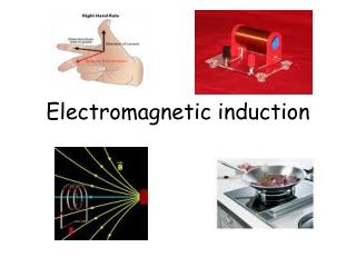
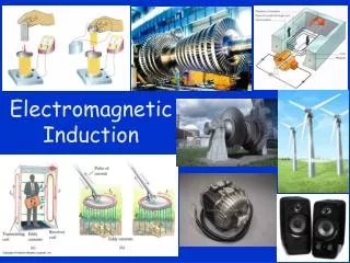
IV. Electromagnetic Induction Further relations between electric and magnetic fields
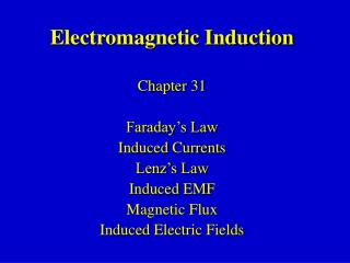
Main Topics • Introduction into Electro-magnetism. • Faraday’s Experiment. • Moving Conductive Rod. • Faraday’s Law. • Lenz’s Law. • Examples
Introduction into Electro-magnetism • Many scientists in history were interested in relation between electric and magnetic fields. When it was known that electric currents producemagnetic fields and interact with them a natural question has appeared: do also magnetic fields produceelectric fields? • Simple experiments somehow didn’t work.
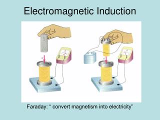
Faraday’s Experiment I • Michael Faraday (1791-1867) used two coils on a single toroidal core. He used a power-source to produce a current through the first coil and he connected galvanometer to the other coil. He probably was not the first one to find out that there was nocurrent through the galvanometer, regardless on how strong the current was.
Faraday’s Experiment II • But he was the first who noticed that the galvanometer deflected strongly when the power source was switched on and it also deflected in the opposite direction when he opened the switch and disconnected the power source. • He concluded that the galvanometer reacts to the changes of the magnetic field.
Simple Demonstration I • We can show the effect of electromagnetic induction and all its qualitative properties even more simply. We need is a permanent magnet and few loops of wire, connected to a galvanometer. • If we move the magnet into the coil the galvanometer moves in onedirection if we move it out the deflection direction changes.
Simple Demonstration II • If we make the experiment more accurately, taking into account which pole of the magnet is the north we find out that the current has such a direction that the field it produces goes against the changes of the external field we do by moving the magnet. • We can also notice that it is sufficient to tilt the magnet and keep in the same distance.
Moving Conductive Rod I • Before we state the general law describing the effect it is useful to study one special case of a conductive rod of a length Lmovingperpendicularlyto the field lines of a uniform magneticfield with a speed v. • Let us expect positive free charge carriers in the rod. Since we force them to move in magnetic field, they experience Lorenzforce.
Moving Conductive Rod II • The charges are free in the rod so they will move and charge one end of the rod positively. • The positive charge will be missing on the other end so an electricfield appears in the rod. Its direction is opposite the the Lorenzforce, so it can be expected the charging will continue only until some equilibrium is reached.
Moving Conductive Rod III • As the charges are positive the equilibrium will be reached when the electric and magnetic forces are equal so the net force on the charges is zero and the charging of the ends thereby stops: qvB = qE = qV/L V = BvL • This is valid regardless on the polarity or the magnitude of the free charge carriers.
The Magnetic Flux I • We have seen that movement of a conductive rod in magnetic field leads to induction of EMF in it. This was a special case of change of a new quantity the flux of the magnetic induction or shortly the magnetic flux.
The Magnetic Flux II • The magnetic flux is defined as dm=B.dA It represents amount of magnetic induction B which flows perpendicularly through a small surface dA, characterized by its outer normal vector. • Remember what exactly the scalar product means!
The Gauss’ Law in Magnetism • The total magnetic flux through a closed surface is always equal to zero! • This is equivalent to the fact that magnetic monopoles don’t exist so the magnetic field is the dipole field and its field lines are always closed. • Any field line which crosses any closed surface must cross it also in again in opposite sense.
The Faraday’s Law I • The general version of Faraday’s law of induction states that the magnitude of the induced EMF in some circuit is equal to the rate of the change of the magnetic flux through this circuit: = - dm/dt • The minus sign describes the orientation of the EMF. A special law deals with that.
The Faraday’s Law II • The magnetic flux is a scalar product of two vectors, the magnetic induction B and A the normal describing the surface of the circuit. So in principle three quantities can change independently to change the magnetic flux: • B … this happens in transformers • A … e.g. in our example with the rod • relative direction of A and B … generators
The Lenz’s Law • The Lenz’s law deals with the orientation of the induced EMF. It states: • An induced EMF gives rise to a current whose magnetic field opposes the original change in flux. • If the circuit is not closed and no current flows we can imagine the directions if it was closed.
Moving Conductive Rod IV • Let’s illustrate Lenz’s law on our moving rod. Now we move it perpendicularly to two parallel rails. • If we connect the rails on the left, the fluxgrows since the area of the circuit grows. The current must be counterclockwise so the field produced by it points into the plane and thereby opposes the grow in flux.
Moving Conductive Rod V • If we connect the rails on the right, the fluxdecreases since the area of the circuit decreases. The current must be clockwise so the field produced by it points out of the plane and thereby opposes the decrease in flux. • Both cases correspond to the orientation of the EMF we have found previously.
Simple Demonstration III • If we return to the demonstration with a permanent magnet and a galvanometer. • From its deflection we can see what is the direction of the the currents in the case we approach the wire loop and the case we leave it. From this we can find which pole of the magnet is the north and verify if in the magnetic field of the Earth.
Rotating Conductive Rod I • A conductive rod L long, is rotating with the angular speed perpendicularly to a uniform magnetic field B.What is the EMF? • The rod is “mowing” the field lines so there is EMF. But each little piece of the rod moves with different velocity. We can imagine the rod like many little batteries in series. So we just integrate their voltages.
Moving Conductive Rod VI • A QUIZ : • Do we have to do work on the conductive rod to move it in magnetic field?
Moving Conductive Rod VII • The answer is: • NO after the equilibrium is reached between electric and magnetic forces and net current doesn’t flow! • The situation will change when we bridge the rails by a resistor. WHY ?
Homework • Chapter 29 – 1, 3, 4, 5, 23, 24, 25
Things to read and learn • Chapter 29 – 1, 2, 3, 5 • Try to understand all the details of the scalar and vector product of two vectors! • Try to understand the physical background and ideas. Physics is not just inserting numbers into formulas!
The vector or cross product I Let c=a.b Definition (components) • The magnitude |c| Is the surface of a parallelepiped made by a,b.
The vector or cross product II The vector c is perpendicular to the plane made by the vectors a and b and they have to form a right-turning system. ijk = {1 (even permutation), -1 (odd), 0 (eq.)} ^
The scalar or dot product Let c=a.b Definition I. (components) Definition II (projection of one vector into the direction of the other one) ^
Gauss’ Law in Magnetism • The exact definition: ^
Rotating Conductive Rod • At first we have to deal with the directions. If the field lines come out of the plane and the rod rotates in positive direction the center of rotation will be negative. dV in dr: • And total EMF: ^