Download
1 / 18
270 likes | 776 Views
Introduction to Arduino. A very basic intro to Arduino, the IDE and the Servos class. The Arduino Board. The Arduino Board. Pins 0-13 can be used for input or output 3 Ground Ports 1 5V Port 1 3.3V Port Some ports support PWM (Pulse Wave Modulation): Ports 3,5,6,10,11

E N D
Introduction to Arduino A very basic intro to Arduino, the IDE and the Servos class
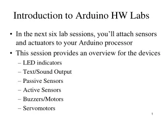
The Arduino Board • Pins 0-13 can be used for input or output • 3 Ground Ports • 1 5V Port • 1 3.3V Port • Some ports support PWM (Pulse Wave Modulation): Ports 3,5,6,10,11 • Ports 0/1 are RX (Receiving), and TX (Sending) – Typically used for Bluetooth Modules/Shields
The IDE • IDE stands for “Integrated Development Environment” – This helps us rapidly develop and deploy programs to our Arduino • Arduino provides a Windows Install File to help us install the IDE and the necessary drivers for communicating with our Arduino
The IDE • The previous slide shows the basic layout when you open the Arduino IDE • Typically, Arduino is coded in C++ -- the compiler/assembler will do the rest • Two methods: setup() and loop() – you may add your own classes for inclusion as well as writing your own methods to be called • Setup() is only called once and is typically used to setup ports on your Arduino among other things • Loop() is where you put code that you want run until you turn off your Arduino
The IDE • As you can see, the IDE is fairly powerful and complete. However, for this tutorial, we are only going to be concerning ourselves with “File” and “Sketch”
Basics of Arduino Programming • Pretty much the same as any other Programming Languages. • Sample Code to turn LEDs on and off on the next page
Sample Code • Int LED0 = 2;intdelay_time = 100;void setup() {pinMode(LED0, OUTPUT);}void loop() {digitalWrite(LED0,HIGH); delay(delay_time);digitalWrite(LED0,LOW);}
Sample Code Breakdown • We declare and initialize a variable “LED0” with our Port number (In this instance, it is 2 but if you had your cable plugged into 13, it would be 13) • We declare and initialize a variable “delay_time.” This sets the time between turning the LED on/off. • Setup() is called and we use pinModeto set LED0 as an Output port on the Arduino. Ports are bi-directional. They can be used as Input or Output.
Sample Code Breakdown • After setup() has finished running, the Arduino then calls loop() • In the loop, we have 2 items: digitalWrite and delay • digitalWrite(LED0,HIGH) turns the LED on • digitalWrite(LED0,LOW) turns the LED off • Delay(delay_time) sets how long it is waiting before the next instruction is run on the Arduino.
Servos • Let’s switch to something a little bit more advanced than LEDs. • Arduino provides a class to power and control Servo motors • See: http://arduino.cc/en/reference/servo • All you do is put #include <Servo.h> before anything else and off you go. • My example will be slightly different
Servo Code • #include <ContinuousRotationServo.h>ContinuousRotationServo Servo;ContinuousRotationServoServoTwo;int timer = 3;void setup() {Servo.begin(13);Servo.begin(12);}void loop() {Servo.rotateLeft(100);ServoTwo.rotateRight(100); delay(timer);}
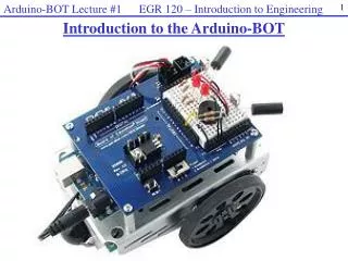
Servos Code Breakdown • We create objects of our ContinuousRotationServo class. • In setup, it is effectively doing the same thing as what we were doing earlier in our LED example. • In loop, we are having the Arduino move one Servo left and one Servo right. In this specific case, the Servos are attached to a Parallax Bo-Bot body with the Arduino and breadboard sitting on top so it is moving in a straight line.
Questions? Comments? • If you have any questions or comments, please register on my website and post on a comment on the Arduino page located on the Computer Science portion of my website. • PPT Last Updated on: 12/26/2013