Download
1 / 24
240 likes | 379 Views
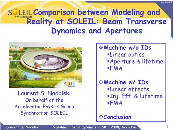
Comparison between Modeling and Reality at SOLEIL: Beam Transverse Dynamics and Apertures. Machine w/o IDs Linear optics Aperture & lifetime FMA Machine w/ IDs Linear effects Inj. Eff. & Lifetime FMA Conclusion. Laurent S. Nadolski On behalf of the Accelerator Physics Group

E N D
Comparison between Modeling and Reality at SOLEIL: Beam Transverse Dynamics and Apertures • Machine w/o IDs • Linear optics • Aperture & lifetime • FMA • Machine w/ IDs • Linear effects • Inj. Eff. & Lifetime • FMA • Conclusion Laurent S. Nadolski On behalf of the Accelerator Physics Group Synchrotron SOLEIL
First day optics Energy tuning • Measurement with quads turned off and turn by turn BPM: DE/E = - 4 10-3 • Agreement with the LT2 dipole calibration • Agreement with the booster beam extraction time • Decision: scaling in energy of all the storage ring magnets: 2.739 GeV Magnet quad. Bench Expected abs. calibration: 2 10-3 But e-beam meas: 12 10-3 Quadrupole tuning based on tune measurement • A relative scaling of all quadrupole gradients of +8 10-3 recovers the tunes • Decision: scaling applied to all quadrupole magnets • Coherence with nominal lattice and Chasman Green lattice • this new calibration gives nx = 18.23 and nz = 10.31 • Relative tune difference is proportional to natural chromaticities • Other solution would have been to change dipole field and to retune storage ring injection
Natural chromaticities X nx Measurement of dipole field performed using NMR probe. Energy offset (%) Z nz The difference in the vertical plane is mainly due to the wrong energy dependence of dipole fringe fields in the model. Energy offset (%)
0.3% rms Reduction of beta-beatingusing LOCO code BPM noise H: 220 nm RMS V: 60 nm RMS
Restoring symmetry of the H-dispersion function • Difficulties using LOCO • Unrealistic quad values (>>%) • 120 BPM/160 quad ratio • Close by quadrupole issues • Modified version of LOCO w/ constraints on gradient variations (see ICFA newsletter, Dec’07) • Results compatible with mag. meas. (10-3 gradient identity, Brunelle et al., EPAC’06) and internal DCCT calibration of individual power supply Quadrupole gradient variations
Linear Model agreement • Orbit, chromaticity, tune response matrices are very closed to real machine • Theoretical values successfully used for • Beam transport matrix for first turn correction (energy calibration, …) • Relative tune shifts • Relative chromaticity shifts • Orbit correction (stable even when using all singular values).
Tune shifts with energy Good Agreement with model DP/P > 0: loss on half Integer resonance (V-plane, 0.02 wide) DP/P < 0: loss on longitudinal beam dynamics xx = +3 xz = +3 Dfrf = +8 kHz DE/E (%) a1 = 4.5 10-4 a2 = 4.6 10-3 DfRF ) fRF
Vertical Acceptance Measured Ixt vs. vertical position of scrapers (up and down) V-scraper is located in a long straight section (200 µm offset) • Measured ~ ± 4.8mm • Expected ± 5.5 mm at scraper position Validity of used method? I·t (mA.h) Simulated Dynamic Aperture (middle of long straight section) z(mm) 4.8 mm Simulations parameters: k = 1% Zmin = ±5mm in medium straight sections Z(mm) X(mm)
Lifetime: Reality vs. modeling 8 bunch operation mode Touschek dominant régime VRF = 2 MV (1CM, 2.9%) Experimental conditions 312 bunches, I = 250 mA, k=0.9 %, VRF = 2.4 MV (1 CM, 3.7%, sl =25ps) Measurement: 17.3h Theory: 16.4 h • Touschek (77 h) • Gas scattering 20 h Good agreement -4.6% and 3.5% momentum acceptance
Experimental DA and FMA Full beam losses @ x = -18.6 mm corresponding to a transverse absorber upstream to U20 (Short SS) nz Z(mm) X(mm) nx Blue circle size: lost rate Red: unstable Black model Zero chromaticities
Insertion Device Effectsinstalled and to come Apple II 3+1x HU80 2+1x HU52 1+1xHU44 1xHU34 Em Fast switching HU640 10 m Full control by users 14 insertion devices In vac. 4+1x U20 1x U24 Em Switching 3x HU256
ID building strategy • Tolerances • A 3 step-process using ID builder (O. Chubar) • Assembly: Module sorting according to magnetic measurements • Minimization of first and second integrals • Shimming: using a merit function • Minimization at different gap and phase values with weight factor • On axis first & second integral (angle & position) in H & V plane • Skew and normal gradient for new IDs • Phase error < 0.2° • Magic fingers (different gap and phase values with weight factor) • Reduction of high field integral for large transverse amplitudes • Expected or unexpected effects depending on gap, phase, current values • Orbit distortion (Feedforward) • Tune, chromaticity, coupling variations • Injection efficiency, lifetime variation (non-linearities, …)
Undulators effects on beam parameters at maximum field Chromaticity variation Tune shifts
Additional focusing (1): Apple II type HU80 ~ Helical Mode (Phase, f = 20 mm) Good agreement with RADIA 2nd order kick map Lin. Horizontal Polar. Mode (f = 0) Lin. Vertical Polar. Mode (f = 40 mm)
Additional focusing (2): in vacuum U20 PX1 SWING Tune shifts expected from design Dnx = 0.00000 Dnz = 0.00169 The construction of these two U20 undulators is based on the same design Gap (mm) Rather large H-tuneshift <bx> = 18 m <bz> = 2 m
Effects of undulators on injection efficiency at maximum field High sensitivity to tune shifts
Strong DA reduction 1 x U20 closed at minimum gap Bare lattice 3 x U20 g = 5.5 mm * Measured for 60mA in 8 bunches VRF = 2.8 MV ; coupling=6.5%
Effects of 3 in-vacuum IDs ! Good agreement Model/Reality ! Dnz = 4.5 10- 3 3nx+nz=65 Combined Effects of IDs deeper
The supposedly perfectlylinear 10 m long HU640 • Electromagnetic insertion device with no iron poles • According to RADIA (model): no effect on non-linear dynamics • Difficulty to ensure high precision magnetic measurement for a 10 m long ID • Assembly/disassembly of the device • On the beam • Skew terms • Strong reduction of injection efficiency • Hysteresis (need for cycling), compromise transparent operation • Worst configuration: PS1=-600 A (LV mode, fast variable polarization in future) HU640 xx=2, xz=2 Strong reduction Bare lattice xx=2, xz=2 PS1=-/+600 A
FMA HU640 & injection efficiencySensitivity to working point 3 x – 2 z = 34 70% 60% x – 4 z = -23 nz 2x + 2 z = 57 90% nx
Effects of undulators on beam lifetimeexamples * Measured for 60mA in 8 bunches VRF = 2.8 MV ; coupling=6.5% * Measured for 202mA in 312 bunches VRF = 2.8 MV ; coupling=0.6%
Effect of the HU640undulator in the LV mode operation Magnetic field +BX max 1.2% BX = 0 0.6% -BX max Coupling Non linear effects + coupling effect +BX max 7h BX = 0 -BX max Beam lifetime Non linear effects
Beam lifetime variation during operation Effect of HU640 undulator Current 1.5h Effect of in vacuum U20 undulators 3h 1 h 1h Beam lifetime reduction due to non linear effects from IDs
Conclusion & perspectives • Machine without insertion devices • Pretty good agreement with the model (H & V acceptances, DA, lifetime) • FMA: first experiments are positive but need further analysis • Insertion devices: good and bad guys • RADIA + tracking simulation codes + magnetic measurement in rather good agreement with e-beam measurements • U20: still question about real physical apertures • Difficult to anticipate all construction and assembly errors • HU640: need to retrofit a model for our simulation • Need strong improvement for injection efficiency and lifetime New working point, coupling correction, feedforward on tunes, FOFB Preparation for top-up operation soon.