Download
1 / 49
490 likes | 513 Views
Learn about 3D translations, scaling, rotations, and rotations along arbitrary axes in computer graphics. Explore the math behind rotation matrices and applying transformations. Understand the graphics pipeline phases, projection types, and the significance of perspective in rendering.

E N D
CAP4730: Computational Structures in Computer Graphics 3D Transformations
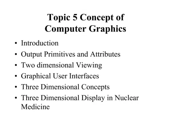
Outline • 3D World • What we are trying to do • Translate • Scale • Rotate
Transformations in 3D! • Remembering 2D transformations -> 3x3 matrices, take a wild guess what happens to 3D transformations. T=(tx, ty, tz)
Scale, 3D Style S=(sx, sy, sz)
Rotations, in 3D no less! What does a rotation in 3D mean? Q: How do we specify a rotation? R=(rx, ry, rz, ) A: We give a vector to rotate about, and a theta that describes how much we rotate. Q: Since 2D is sort of like a special case of 3D, what is the vector we’ve been rotating about in 2D?
Rotations about the Z axis What do you think the rotation matrix is for rotations about the z axis? R=(0,0,1,)
Rotations about the X axis Let’s look at the other axis rotations R=(1,0,0,)
Rotations about the Y axis R=(0,1,0,)
Rotations for an arbitrary axis u Steps: 1. Normalize vector u 2. Compute 3. Compute 4. Create rotation matrix
Vector Normalization • Given a vector v, we want to create a unit vector that has a magnitude of 1 and has the same direction as v. Let’s do an example.
Computing the Rotation Matrix • 1. Normalize u • 2. Compute Rx() • 3. Compute Ry() • 4. Generate Rotation Matrix
Applying 3D Transformations P’=TRTP Let’s compute M
Homogenous Coordinates • We need to do something to the vertices • By increasing the dimensionality of the problem we can transform the addition component of Translation into multiplication.
Homogenous Coordinates • Homogenous Coordinates – embed 3D transforms into 4D • All transformations can be expressed as matrix multiplications. • Inverses and combination easier • Equivalence of vectors (4 2 1 1)=(8 4 2 2) • What this means programatically
The Question • Given a 3D point, an eye position, a camera position, and a display plane, what is the resulting pixel position? • Now extend this for a group of three points • Then apply what you know about scan conversion.
Let’s Examine the Camera • If I gave you a world, and said I want to “render” it from another viewpoint, what information do I have to give you? • Position • Which way we are looking • Which way is “up” • Aspect Ratio • Field of View • Near and Far
Camera View Right View Up View Normal View Direction
Camera View Up View Right What are the vectors?
Graphics Pipeline So Far Object Object Coordinates Transformation Object -> World World World Coordinates Projection Xform World -> Projection Normalize Xform & Clipping Projection -> Normalized Camera Projection Coordinates Viewport Normalized Coordinates Viewport Transform Normalized -> Device Screen Device Coordinates
Transformation World->Camera View Right View Up View Normal View Direction
Transformation World->Camera View Right = u View Up = V View Direction = -N
u Cross Products Given two vectors, the cross product returns a vector that is perpendicular to the plane of the two vectors and with magnitude equal to the area of the parallelogram formed by the two vectors.
Parallel Projections (known aliases): Orthographic or Isometric Projection
Parallel Projections (known aliases): Oblique Projection L
Projections foreshortening - the farther an object is from the camera , the smaller it appears in the final image
Perspective Projection Side View P=(xp,yp,zp) t=0 P’=(x’,y’,z’) t=? C=(xc,yc,zc) t=1 xp x’ z’ zp
Perspective Projection Side View P=(xp,yp,zp) t=0 P’=(x’,y’,z’) t=? C=(xc,yc,zc) t=1 xp h x’ z’ zp Scale by h
Perspective Divide Foreshortening - look at the x,y, and w values, and how they depend on how far away the object is. Modelview Matrix - describes how to move the world->camera coordinate system Perspective Matrix - describes the camera you are viewing the world with.
What the Perspective Matrix means Note: Normalized Device Coordinates are a LEFT-HANDED Coordinate system
Graphics Pipeline So Far Object Object Coordinates Transformation Object -> World World World Coordinates Projection Xform World -> Projection Normalize Xform & Clipping Projection -> Normalized Camera Projection Coordinates Viewport Normalized Coordinates Viewport Transform Normalized -> Device Screen Device Coordinates
What happens to an object... Transformation Object -> World Object Object Coordinates World World Coordinates
What happens to an object... Transformation - Modelview World -> Eye/Camera World World Coordinates Viewport Viewport Coordinates
What happens to an object... Transformation - Projection (Includes Perspective Divide) Eye/Camera ->View Plane Viewport Viewport Coordinates Rasterization Scan Converting Triangles
Normalized Screen Coordinates Let’s label all the vectors znsc=0 znsc=1
View Volume (View Frustum) Usually: View Plane = Near Plane Far Plane -1,1,1 Mperspective_Matrix Think about: Clipping 3D Triangles View Frustum Culling 1,-1,-1
Let’s verbalize what’s going on • Review: • Pipeline • Series of steps • What we’ll do next: • Hidden Surface Removal • Depth Buffers • Lighting • Shading • Blending (the elusive alpha) • Textures