Download
1 / 34
360 likes | 564 Views
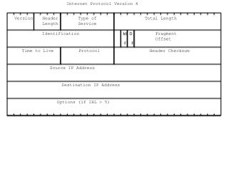
The IP Version 4 Protocol . The IPv4 (Internet Protocol) header. IP protocol version number. 32 bits. total datagram length (bytes). header length (bytes). type of service. head. len. ver. length. for fragmentation/ reassembly. fragment offset. “type” of data . flgs.

E N D
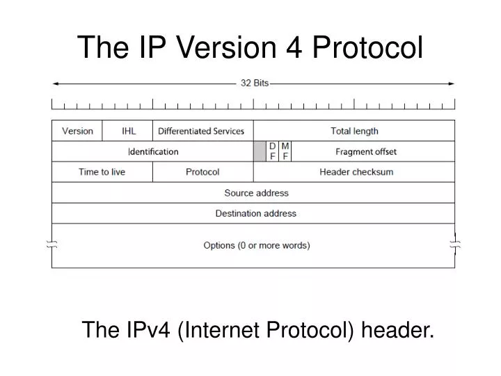
The IP Version 4 Protocol The IPv4 (Internet Protocol) header.
IP protocol version number 32 bits total datagram length (bytes) header length (bytes) type of service head. len ver length for fragmentation/ reassembly fragment offset “type” of data flgs 16-bit identifier max number remaining hops (decremented at each router) upper layer time to live header checksum 32 bit source IP address 32 bit destination IP address upper layer protocol to deliver payload to E.g. timestamp, record route taken, specify list of routers to visit. Options (if any) data (variable length, typically a TCP or UDP segment) IP datagram format how much overhead with TCP? • 20 bytes of TCP • 20 bytes of IP • = 40 bytes + app layer overhead Network Layer
IPv6 • Initial motivation:32-bit address space soon to be completely allocated. • Additional motivation: • header format helps speed processing/forwarding • header changes to facilitate QoS IPv6 datagram format: • fixed-length 40 byte header • no fragmentation allowed
IPv6 Header (Cont) Priority: identify priority among datagrams in flow Flow Label: identify datagrams in same “flow.” (concept of“flow” not well defined). Next header: identify upper layer protocol for data
Other Changes from IPv4 • Checksum:removed entirely to reduce processing time at each hop • Options: allowed, but outside of header, indicated by “Next Header” field • ICMPv6: new version of ICMP • additional message types, e.g. “Packet Too Big” • multicast group management functions
Transition From IPv4 To IPv6 • Not all routers can be upgraded simultaneous • How will the network operate with mixed IPv4 and IPv6 routers? • Tunneling: IPv6 carried as payload in IPv4 datagram among IPv4 routers
Tunneling (1) Tunneling a packet from Paris to London.
used by hosts & routers to communicate network-level information error reporting: unreachable host, network, port, protocol echo request/reply (used by ping) network-layer “above” IP: ICMP msgs carried in IP datagrams ICMP message: type, code plus first 8 bytes of IP datagram causing error ICMP: Internet Control Message Protocol TypeCodedescription 0 0 echo reply (ping) 3 0 dest. network unreachable 3 1 dest host unreachable 3 2 dest protocol unreachable 3 3 dest port unreachable 3 6 dest network unknown 3 7 dest host unknown 4 0 source quench (congestion control - not used) 8 0 echo request (ping) 9 0 route advertisement 10 0 router discovery 11 0 TTL expired 12 0 bad IP header Network Layer
Source sends series of UDP segments to dest First has TTL =1 Second has TTL=2, etc. Unlikely port number When nth datagram arrives to nth router: Router discards datagram And sends to source an ICMP message (type 11, code 0) Message includes name of router& IP address When ICMP message arrives, source calculates RTT Traceroute does this 3 times Stopping criterion UDP segment eventually arrives at destination host Destination returns ICMP “host unreachable” packet (type 3, code 3) When source gets this ICMP, stops. Traceroute and ICMP Network Layer
ARP (logical to Physical address mapping) • ARP (Address Resolution Protocol) is used in Ethernet Networks to find the MAC address of a node given its IP address. • Source node (say 192.168.2.32) sends broadcast message (ARP Request) on its subnet asking ``Who is 192.168.2.33’’. • All computers on subnet receive this request • Destination responds (ARP Reply) since it has 192.168.2.33 • Provides its MAC address in response
Question: how to determine MAC address of B knowing B’s IP address? ARP: Address Resolution Protocol • Each IP node (host, router) on LAN has ARP table • ARP table: IP/MAC address mappings for some LAN nodes < IP address; MAC address; TTL> • TTL (Time To Live): time after which address mapping will be forgotten (typically 20 min) 137.196.7.78 1A-2F-BB-76-09-AD 137.196.7.23 137.196.7.14 LAN 71-65-F7-2B-08-53 58-23-D7-FA-20-B0 0C-C4-11-6F-E3-98 137.196.7.88
A wants to send datagram to B, and B’s MAC address not in A’s ARP table. A broadcasts ARP query packet, containing B's IP address dest MAC address = FF-FF-FF-FF-FF-FF all machines on LAN receive ARP query B receives ARP packet, replies to A with its (B's) MAC address frame sent to A’s MAC address (unicast) A caches (saves) IP-to-MAC address pair in its ARP table until information becomes old (times out) soft state: information that times out (goes away) unless refreshed ARP is “plug-and-play”: nodes create their ARP tables without intervention from net administrator ARP protocol: Same LAN (network)
88-B2-2F-54-1A-0F 74-29-9C-E8-FF-55 E6-E9-00-17-BB-4B 222.222.222.221 1A-23-F9-CD-06-9B 111.111.111.111 222.222.222.222 222.222.222.220 111.111.111.110 R 111.111.111.112 49-BD-D2-C7-56-2A CC-49-DE-D0-AB-7D A B Addressing: routing to another LAN walkthrough: send datagram from A to B via R assume A knows B’s IP address • two ARP tables in router R, one for each IP network (LAN)
88-B2-2F-54-1A-0F 74-29-9C-E8-FF-55 E6-E9-00-17-BB-4B 222.222.222.221 1A-23-F9-CD-06-9B 111.111.111.111 222.222.222.222 222.222.222.220 B A 111.111.111.110 R 111.111.111.112 49-BD-D2-C7-56-2A CC-49-DE-D0-AB-7D This is a really important example – make sure you understand! • A creates IP datagram with source A, destination B • A uses ARP to get R’s MAC address for 111.111.111.110 • A creates link-layer frame with R's MAC address as dest, frame contains A-to-B IP datagram • A’s NIC sends frame • R’s NIC receives frame • R removes IP datagram from Ethernet frame, sees its destined to B • R uses ARP to get B’s MAC address • R creates frame containing A-to-B IP datagram sends to B
RARP(Physical to logical address mapping) • Broadcasting a request message for IP address on the network. • Use of RARP is better than embedding IP address in memory image (for diskless workstation). • Need separate RARP server for each network.
BOOTP(bootstrap protocol) • Uses UDP message which are forwarded over router. • Provide additional information including IP address of file server holding memory image, subnet mask. • It require manual configuration of table mapping IP address to Ethernet address.
DHCP(Dynamic host configuration protocol) • Allows both manual or automatic IP address assignment. • To share DHCP server we require relay agent on each LAN. • Newly booted host broadcast a DHCP DISCOVER packet. • For efficient utilization IP address DHCP server uses leasing technique.
Multiprotocol label switching (MPLS) Transmitting a TCP segment using IP, MPLS, and PPP.
Multiprotocol label switching (MPLS) Forwarding an IP packet through an MPLS network
MPLS capable routers • label-switched router • forwards packets to outgoing interface based only on label value (don’t inspect IP address) • MPLS forwarding table distinct from IP forwarding tables • signaling protocol needed to set up forwarding • forwarding possible along paths that IP alone would not allow (e.g., source-specific routing) !! • use MPLS for traffic engineering • must co-exist with IP-only routers 5: DataLink Layer
in out out label label dest interface 10 6 A 1 12 9 D 0 in out out label label dest interface in out out label label dest interface 8 6 A 0 6 - A 0 MPLS forwarding tables in out out label label dest interface 10 A 0 12 D 0 8 A 1 R6 0 0 D 1 1 R3 R4 R5 0 0 A R2 R1 5: DataLink Layer
Subnetting in Classful Addresses Classful addressing in IP is both inflexible and inefficient ! allows 127 networks and 16 777 214 hosts on each network allows 16384 networks and 65534 hosts on each network allows 2 097 152 networks and 254 hosts on each network
Need for Subnetting • Classes A and B have a large number of hosts corresponding to each network ID • It may be desirable to subdivide the hosts in Class C subnets • Often, there is a limitation on the number of hosts that could be hosted on a single network segment • The limitation may be imposed by concerns related to the management of hardware • Smaller broadcast domains are more efficient and easy to manage
10000000 00010100 00000000 00000000 Class B addess Network Prefix Host Suffix Subnetting with /20 mask Network Prefix Host ID Subnet ID Subnetting in Classful Addresses 128.20.0.0
10000000 01101111 11000000 11001010 11111111 11111111 11111111 11111000 Network ID: 128.111.192.200 Classless InterDomain Routing (CIDR) Addressing in Internet Protocol CIDR allows each IP address to have a different length of network ID and host ID. In CIDR each IP address is assigned a 32-bit mask to extract the network ID. 128.111.192.202 / 29 10000000 01101111 11000000 11001000
10011001 11101101 01101100 11100011 11111111 11111111 11100000 00000000 Network ID: 153.237.96. 0 Classless InterDomain Routing (CIDR) Addressing in Internet Protocol 153.237.108.227 /19 10011001 11101101 01100000 00000000
Classless InterDomain Routing (CIDR) Addressing in Internet Protocol 128.192.111.192 /29 128.192.111.194 /29 128.192.111.194 /29 128.192.111.200 /29 128.192.111.202 /29 128.192.111.201 /29 128.192.111.192 /28 10000000 11000000 01101111 1100000
Routing Tables in IP with CIDR For each entry in the routing table: MaskedAddress := EntryMask (bitAND) IPDatagramDestinationAddress; if (MaskedAddress == EntryDestination) Mark the entry; Choose the marked entry with the longest Mask prefix.
VLAN VLANs • VLANs (Virtual LAN) enable network managers to group users logically (based on functions, project teams or applications) rather than by physical location. • Traffic can only be routed between VLANs. • VLANs provide the segmentation traditionally provided by physical routers in LAN configuration.
VLAN VLANs and Inter VLAN Routing
VLAN Advantages of Using VLANs • Broadcast Control— Just as switches physically isolate collision domains for attached hosts and only forward traffic out a particular port, VLANs provide logical bridging domains that confine broadcast and multicast traffic to the VLANs. • Security— If you do not allow routing in a VLAN, no users outside of that VLAN can communicate with the users in the VLAN and vice versa. This extreme level of security can be highly desirable for certain projects and applications. • Performance— You can assign users that require high-performance or isolated networking to separate VLANs.