Download

1 / 18
732 likes | 1.53k Views
The Potential Divider. Electricity Lesson 10. Learning Objectives. To know what a potential divider is. To derive and know how to use the potential divider equation. To know that the load affects the output of a potential divider

E N D
The Potential Divider Electricity Lesson 10
Learning Objectives To know what a potential divider is. To derive and know how to use the potential divider equation. To know that the load affects the output of a potential divider To know the applications of potential dividers; to detect temperature or light levels.
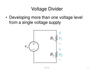
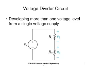
Definition What is potential divider? A potential divider consists of two or more resistors connected in series with each other and a source of fixed potential difference. Draw a circuit diagram for this arrangement.
Circuit Diagram What is the pd across each resistor? We can use potential difference between points A and B as a supply for another component.
Uses of a Potential Divider To supply a fixed pd between any value between zero and the source pd. To supply a variable pd from a fixed one. To supply a pd that varies with physical changes e.g. position, temperature or light level
V2 R2 VS R1 V1 Another Example
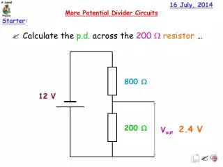
Supplying a fixed pd The total resistance of the circuit = R1 + R2 The current through the resistors = V0/(R1 + R2)
Deriving Potential divider equation • For an unloaded potential divider the current is the same through both resistors • So the voltage is proportional to the resistance
Potential divider equation • If R1 >> R2 then V1 is more or less the supply voltage • If R1 << R2 then V1 is close to 0 V. • V0 as an input to the potential divider and V1 as an output. The circuit itself provides a way to tap off a voltage between 0 V and V0.
Confused? So what’s the difference between a variable resistor and a potential divider?
Confused? When a variable resistor is used the total resistance of the circuit is being altered. Also, the pd is not being taken across the variable resistor.
VINV V out
Using potential dividers • Use as a volume, brightness or contrast control. • Making and designing a circuit to use as a temperature sensor • Making and designing a circuit to use as a light sensor • Controlling logic devices
Effect of different resistive loads • Output voltage is affected by load resistance • Connecting a resistor across the output reduces the output voltage • Shorting out across a bulb reduces the total resistance of the bulb – the wire is in parallel with the bulb
Questions • A series circuit is connected as shown in the diagram. • 1. What is the potential difference between A and B? • 2. An additional resistor of 100 W is connected between the 50 W resistor and the cells. What is the potential difference between A and B now? • 3. The additional 100 W resistor is now connected in parallel with the first 100 W resistor. What is the potential difference between A and B now?
Question • How do we get a variable supply voltage from a fixed one? • How can we measure physical changes in position, temperature or light level etc.
Answer • A potential divider is one way of producing a variable p.d. • A combination of a suitable sensor (angle / position sensor, thermistor or LDR) and a potential divider enables measurement / monitoring / control of physical changes.
Alternative formula • The potential divider equation can be derived by rearranging the ratios above to give: • V output = R1 / (R1+R2) V input.