Download
1 / 73
760 likes | 1.11k Views
Chapter 2, Modeling with UML. Overview: modeling with UML. What is modeling What is UML? Use case diagrams Class diagrams Sequence diagrams Activity diagrams. What is modeling?. Modeling consists of building an abstraction of reality Abstractions are simplifications because:

E N D
Overview: modeling with UML • What is modeling • What is UML? • Use case diagrams • Class diagrams • Sequence diagrams • Activity diagrams
What is modeling? • Modeling consists of building an abstraction of reality • Abstractions are simplifications because: • They ignore irrelevant details and • They only represent the relevant details • What is relevant or irrelevant depends on the purpose of the model
Why model software? Why model software? • Software is getting increasingly more complex • Modeling is a means for dealing with complexity
Systems, Models and Views • A model is an abstraction describing a subset of a system • A view depicts selected aspects of a model • Simplifies a complex model – subset of a model to make it understandable • A notation is a set of graphical or textual rules for depicting views • Views and models of a single system may overlap each other Examples: • System: Aircraft • Models: Flight simulator, scale model • Views: electrical wiring, fuel system (views of the scale model)
Systems, Models and Views Scale model Blueprints Aircraft Electrical Wiring Flight Simulator
Concepts in software: Data Type and Instance • Data Type • An abstraction in the context of programming languages • Has name, members, and valid operations • Name: int • Members: 0, -1, 1, 2, -2, . . .(all signed integers between -232 and 232) • Operations: +, -, *, integer /, mod, . . . • Instance • Member of a specific type • The type of a variable represents all possible instances the variable can take
Abstract Data Types & Classes • Abstract data type • Special type whose implementation is hidden from the rest of the system. • E.g. set, stack, etc. • Class • An abstraction in the context of object-oriented languages • Like an abstract data type, a class encapsulates both state (variables) and behavior (methods) • Unlike abstract data types, classes can be defined in terms of other classes using inheritance
Objects • Object • Instance of a class • Represented by a rectangle with name underlined • Notice: CalculatorWach1515 is a watch but it is not an instance of Watch «instanceOf» simpleWatch1291:Watch Watch «instanceOf» calculatorWatch1515 :CalculatorWatch CalculatorWatch
Fruit Collection Orange Apple LinkedList HashMap Subclasses and Superclasses • Superclass • Generalization class • Subclass • Specialization of its superclass • Refines the superclass by defining new attributes and operations • Abstract class • Generalized concepts that model shared attributes and operations • Can not be instantiated • Name italicized • E.g.,
Application and Solution Domain • Application Domain (Requirements Analysis): • Represents aspects of the user’s problem • Environment of the system, users, work processes, etc. • Solution Domain (System Design, Object Design): • The available technologies to build the system
Object-oriented modeling Application Domain Solution Domain Application Domain Model (OO Analysis) System Model (OO Design) UML Package MapDisplay TrafficControl SummaryDisplay FlightPlanDatabase TrafficController Aircraft Airport TrafficControl FlightPlan
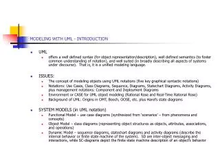
What is UML? • “The UML is the standard language for specifying, visualizing, constructing, and documenting all the artifacts of a software system.” • An emerging standard notation (by Object Management Group--OMG) for modeling object-oriented software • Unified Modeling Language • Effective for modeling large, complex software systems • It can specify systems in an implementation-independent manner • It is simple to learn for most developers, but provides advanced features for expert analysts, designers and architects • 20% of the constructs are used 80% of the time
About UML? • Resulted from the convergence of notations from three leading object-oriented methods (early 90’s: • OMT (James Rumbaugh) • OOSE (Ivar Jacobson) • Booch (Grady Booch) • The above three OO gurus joined forces in one company, Rational (now IBM) • ROSE, Rational Unified Process (RUP), UML • Supported by several CASE tools • Rational ROSE • TogetherJ • Eclipse UML plugin (in our lab)
UML: First Pass • You can model 80% of most problems by using about 20 % UML • We will see these 20%
UML First Pass • Use case Diagrams • Describe the functional behavior of the system as seen by the user. • Class diagrams • Describe the static structure of the system: Objects, Attributes, Associations • Sequence diagrams • Describe the dynamic behavior between actors and the system and between objects of the system • Statechart diagrams • Describe the dynamic behavior of an individual object (essentially a finite state automaton) • Activity Diagrams • Model the dynamic behavior of a system, in particular the data flow or control flow through a system (essentially a flowchart)
Watch ReadTime SetTime WatchUser WatchRepairPerson ChangeBattery UML first pass: Use case diagrams Use case Package Actor Use case diagrams represent the functionality of the system from user’s point of view
1 1 1 2 1 1 LCDDisplay Battery load Time now blinkIdx blinkSeconds() blinkMinutes() blinkHours() stopBlinking() referesh() UML first pass: Class diagrams Class diagrams represent the structure of the system Association Class Multiplicity Watch 1 2 PushButton state push()release() Attribute Operations
:Watch :LCDDisplay :Time :WatchUser pressButton1() blinkHours() pressButton1() blinkMinutes() pressButton2() incrementMinutes() refresh() pressButtons1And2() commitNewTime() stopBlinking() UML first pass: Sequence diagram Actor Object Message Activation Lifeline Sequence diagrams represent the behavior as interactions
UML first pass: Statechart diagrams for objects with interesting dynamic behavior State Event Initial state Transition Final state Represent behavior as states and transitions
Other UML Notations UML provide other notations that we will be introduced in subsequent lectures, as needed. • Implementation diagrams • Component diagrams • Deployment diagrams • Introduced in lecture on System Design • Object constraint language • Introduced in lecture on Object Design
UML Core Conventions • Rectangles are classes or instances • Ovals are functions or use cases • Instances are denoted with an underlined names • myWatch:SimpleWatch • Joe:Firefighter • Types are denoted with non underlined names • SimpleWatch • Firefighter • Diagrams are graphs • Nodes are entities • Arcs are relationships between entities
What is a Use Case Model? • A view of a system that emphasizes the behavior as it appears to outside users. A use case model partitions system functionality into transactions (‘use cases’) that are meaningful to users (‘actors’). • Actors represent external entities, E.g., • Roles: user, bank teller, customer, system administrator • Other systems: company DB, Web server, etc. • Use cases represent a sequence of interaction for a type of functionality • The use case model is the set of all use cases. It is a complete description of the system functionality.
Passenger PurchaseTicket Use Case Diagram • Shows use cases, actor and their relationships • Use case internals are typically specified by textual description • Use case include • use case diagram • use case description
An actor models an external entity which communicates with the system: User External system Physical environment An actor has a unique name and an optional description. Examples: Passenger: A person in the train GPS satellite: Provides the system with GPS coordinates Passenger Actors
A use case represents a class of functionality provided by the system. A use case consists of: Unique name Participating actors Entry conditions Flow of events Exit conditions Special requirements PurchaseTicket Use Case
Name:Purchase ticket Participating actor:Passenger Entry condition: Passenger standing in front of ticket distributor. Passenger has sufficient money to purchase ticket. Exit condition: Passenger has ticket. Event flow: 1. Passenger selects the number of zones to be traveled. 2. Distributor displays the amount due. 3. Passenger inserts money, of at least the amount due. 4. Distributor returns change. 5. Distributor issues ticket. Use Case Description: Example Anythingmissing? Exceptional cases!
<<extends>> relationships represent exceptional or seldom invoked cases. The exceptional event flows are factored out of the main event flow for clarity. Use cases representing exceptional flows can extend more than one use case. The direction of a <<extends>> relationship is to the extended use case Passenger PurchaseTicket <<extends>> OutOfOrder TimeOut <<extends>> <<extends>> <<extends>> Cancel NoChange The <<extends>> Relationship
<<includes>> relationship represents behavior that is factored out of the use case. <<includes>> behavior is factored out for reuse, not because it is an exception. The direction of a <<includes>> relationship is to the using use case (unlike <<extends>> relationships). Passenger PurchaseMultiCard PurchaseSingleTicket <<includes>> <<includes>> NoChange Cancel CollectMoney <<extends>> <<extends>> The <<includes>> Relationship
Used when one use case can specialize another more general one by adding more detail In the use case description the specialized use case inherits the initiating actor, the entry condition, and the exit condition. The InheritanceRelationship Authenticate WithPassword Authenticate Authenticate WithCard
Use Case Relationships Summary <<extend>> <<include>>
Use Case Diagram Example Fig. 3-53, UML Notation Guide
Use Case Relationships Example Fig. 3-54, UML Notation Guide
Use Case Diagrams: Summary • Use case diagrams represent external behavior • Use case diagrams are useful as an index into the use cases (descriptions) • Use case descriptions provide meat of model, not the use case diagrams. • All use cases need to be described for the model to be useful. • Use cases can be used for • Model user requirements • Model test scenarios
zone:Zone Price: Price TarifSchedule Trip Class Diagrams • Class diagrams represent the structure of the system. • Used • during requirements analysis to model problem domain concepts • during system design to model subsystems and interfaces • during object design to model classes. Enumeration getZones() Price getPrice(Zone) * *
TarifSchedule TarifSchedule TarifSchedule Table zone2price Enumeration getZones() Price getPrice(Zone) zone2price getZones() getPrice() Classes Name Signature Attributes Operations • A class represent a concept • A class encapsulates state (attributes) and behavior (operations). • Each attribute has a type. • Each operation has a signature. • The class name is the only mandatory information.
tarif_1974:TarifSchedule Instances zone2price = { {‘1’, .20},{‘2’, .40}, {‘3’, .60}} • An instance represents a phenomenon. • The name of an instance is underlined and can contain the class of the instance. • The attributes are represented with their values.
TarifSchedule TripLeg Associations Enumeration getZones() Price getPrice(Zone) PriceZone * * • Associations denote relationships between classes. • The multiplicity of an association end denotes how many objects the source object can legitimately reference.
1-to-1 and 1-to-many Associations Has-capital Country City name:String name:String One-to-one association Point * Polygon x: Integer y: Integer draw() One-to-many association
Many-to-Many Associations Lists * * Company StockExchange tickerSymbol
From Problem Statement To Object Model Pr oblem Statement: A stock exchange lists many companies. Each company is uniquely identified by a ticker symbol Class Diagram: Company * * StockExchange Lists tickerSymbol
From Problem Statement to Code Pr oblem Statement : A stock exchange lists many companies. Each company is identified by a ticker Symbol Class Diagram: * * Company StockExchange Lists tickerSymbol Java Code public class StockExchange { private Vector m_Company = new Vector(); }; public class Company { public int m_tickerSymbol; private Vector m_StockExchange = new Vector(); };
Exhaust system TicketMachine ZoneButton 0..2 1 Muffler Tailpipe diameter diameter Aggregation • An aggregation is a special case of association denoting a “consists of” hierarchy. • The aggregate is the parent class, the components are the children class. • A solid diamond denotes composition, a strong form of aggregation where components cannot exist without the aggregate. (Bill of Material) 3
Without qualification File 1 * Directory filename With qualification 1 0…1 Directory filename File Qualifiers • Qualifiers can be used to reduce the multiplicity of an association.
CancelButton ZoneButton Button Inheritance • The children classes inherit the attributes and operations of the parent class. • Inheritance simplifies the model by eliminating redundancy.
Object Modeling in Practice: Class Identification Foo Betrag CustomerId Deposit() Withdraw() GetBalance() Class Identification: Name of Class, Attributes and Methods