Download
1 / 15
150 likes | 346 Views
CCD Camera Realignment. CCD Camera Realignment. Increasing Visual Representation of Video. David Medeiros Institution: Maui Community College Site Manager: Albert Esquibel. 1. Northrop Grumman. Northrop Grumman. Northrop Grumman is a global defense and technology company

E N D
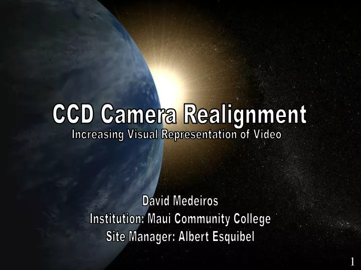
CCD Camera Realignment CCD Camera Realignment Increasing Visual Representation of Video David Medeiros Institution: Maui Community College Site Manager: Albert Esquibel 1
Northrop Grumman Northrop Grumman • Northrop Grumman is a global defense and technology company • Company does business around the world • Contracted by US Air force 2
GEODSS GEODSS Ground-based Electro Optical Deep Space Surveillance • GEODSS has three sites around the globe • All GEODSS sites maintain and operate 3-1.0 meter telescopes 3
Assignment Assigned Task The assigned project task was to develop and assess the GEODSS camera head assembly and determine the most feasible solution to correct an existing situation with the CCD camera. GEODSS personnel were assigned to educate me on the system and guide me with possible solutions for my assessment. 4
What is CCD ? What is CCD ? • Charge-Coupled Device • Resolution 2560x1960 • CCD uses a rectangular piece of silicon • Pixels Charge converted into electrons 5
Signal Flow of GEODSS Camera How GEODSS CCD Camera Operates • Video output of the CCD arrays are sent • The signal then gets amplified • A/D converter then adjust the gain accordingly 6
Project Description Project Description • Degraded video segment • Currently port #4 on one of the three GEODSS sensor CCD ports is being blocked out • Our goal is to decrease the current video loss 7
Plan of Action Plan of Action • As a provisional fix the system software will be modified • Software manipulation is the safest and easiest way to fix the current situation • It was determined that pulling the camera could possibly cause camera failure • In the event problems arise, easier to revert back to normal configuration through software. 8
Steps-to-Take Steps-to-Take • Install a backup drive with preinstalled software • Modify camera initialization • Run simulated calibrations • Capture FITS Image and view in imaging software • Identify bad pixels and record values • Enter new values in initialization file • Run multiple camera calibrations • Place system back into operations 9
0 2559 979 2466 1959 Viewing of FITS Image Viewing of FITS Image • Flexible Image Transport System • Measuring of pixels to acquire greater field-of-view 10
Calibrations and Results Calibrations and Results • 3 Calibrations will be performed (channel offset, dark current and flat field) • Channel offset mean values need to be within + or – 1 • Dark Current noise value < 50 counts • Flat Field between .5 to 2.5 counts • Validation of Data 11
Conclusion Steps-to-Take • Install a backup drive with preinstalled software • Modify camera initialization • Run simulated calibrations • Capture FITS Image and view in imaging software • Identify bad pixels and record values • Enter new values in initialization file • Run multiple camera calibrations • Place system back into operations 9
Expected Results Expected Results • Increase in throughput • Improvement of search based operations • Improvement with serendipitous observations 12
Center for Adaptive Optics Hillary O’Brian Scott Seagroves Lisa Hunter Northrop Grumman Albert Esquibel & Staff Maui Community College Mark Hoffman 2007 Short Course/Internship David Harrington Jess Johnson Ryan Montgomery Isar Mostafanezhad Fellow Interns Maui Economical Development Board Isla Yap Leslie Wilkins Acknowledgments Acknowledgments • Institute for Astronomy Funding Provided through the Center for Adaptive Optics, National Science Foundation, Science and Technology Center (STC), AST-987683 14
Questions Questions ? 15