Download
1 / 54
590 likes | 1.26k Views
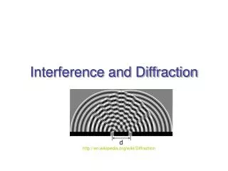
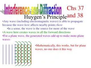
Diffraction at Multiple Slits and Diffraction Gratings. The role of Interference. For multiple apertures, the effects of interference and diffraction cannot be readily separated . Diffraction at Multiple Slits and Diffraction Gratings. The role of Interference.

E N D
Diffraction at Multiple Slits and Diffraction Gratings. The role of Interference For multiple apertures, the effects of interference and diffraction cannot be readily separated
Diffraction at Multiple Slits and Diffraction Gratings. The role of Interference In Young’s Double Slit experiment, diffraction must have been occurring as well as interference Narrow slits minimize any visible role of diffraction in the screen intensity profile
Diffraction at Multiple Slits and Diffraction Gratings. The role of Interference The same mathematical constructions as for diffraction are used to define path length differences leading to interference minima and maxima
Waves traveling to point P on screen A E q q d D C B Double Slit Interference: Path Difference Double Slit to central maximum Fig 32 Page 43
d _ BC = l Waves traveling to point Q on screen corresponding to . Waves in phase constructive interference DOUBLE SLIT INTERFERENCE A to central maximum q q B C When BC = , waves traveling through the two slits are in phase because their path difference is equal to Fig 33 Page 45
Slit to P A 0 d D B _ C BC = l Diffraction - First Order Minimum SINGLE SLIT DIFFRACTION to P Each wave through upper half cancels corresponding wave through lower half of slit destructive interference Fig 34b Page 46
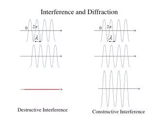
I interference plus diffraction diffraction only q I q Intensity Profile - Interference vs. Diffraction Double slit interference narrow slits Double slit interference wider slits Fig 35 Page 43
Interference Maxima: Young’s Double Slit Source Slit Double Slit (m = 0 · · · · · · · 6)
Practice Problem 1 Yellow light ( = 595 nm) is used to produce interferencefringes with Young’s double-slit set-up. Find angular location of the third order interference maximum for a slit separation of 0.10 mm: • 0.349O • 1.023O • 1.875O • 3.550O
Source Slit Double Slit
Practice Problem 1 Yellow light ( = 595 nm) is used to produce interferencefringes with Young’s double-slit set-up. Find angular location of the third order interference maximum for a slit separation of 0.10 mm: • 0.349O • 1.023O • 1.875O • 3.550O
Practice Problem 2 For the same interference set-up (slit separation 0.10 mm; yellow light, = 595 nm), find linear position on the screen of the third order interference maximum if the screen is 7.5 meters from the double slit • 4.95 cm • 7.03 cm • 11.95 cm • 13.39 cm
= 7.5 meters Source Slit
Source Slit x = 7.5 meters
Practice Problem 2 For the same interference set-up (slit separation 0.10 mm; yellow light, = 595 nm), find linear position on the screen of the third order interference maximum if the screen is 7.5 meters from the double slit • 4.95 cm • 7.03 cm • 11.95 cm • 13.39 cm
Interference Pattern for Relatively Narrow Slits Source Slit Double Slit
Source Slit Double Slit Widen the slits in the Double Slit
Source Slit Double Slit Farther widen the slits in the double slit
Source Slit Double Slit Slits wider again: almost an entire diffraction max
Source Slit Double Slit Farther widen the slits in the double slit As the slits become wider, the first order diffraction minimum moves closer to the center of the screen profile
Double Slit Interference: Diffraction versus Slit Width For narrow slits, the angle of the first order diffraction minimum is >> than that of the first order interference maximum
Double Slit Interference: Diffraction versus Slit Width As the slits become wider, the angle of diffraction decreases, and diffraction has a more visible effect on the screen intensity profile
A B Practice Problem 3 The two figures below show screen intensity profiles for a double slit. Slit separation is the same in both cases, but slit width differs. In which figure are the slits wider? 1st order Diffraction minimum Interference maxima
Practice Problem 3 The two figures below show screen intensity profiles for a double slit. Slit separation is the same in both cases, but slit width differs. In which figure are the slits wider? 1st order Diffraction minimum A B
Practice Problem 3 The two figures below show screen intensity profiles for a double slit. Slit separation is the same in both cases, but slit width differs. In which figure are the slits wider? A B
Practice Problem 4 All four figures show screen intensity profiles for a double slit. In which figure is the slit separation greatest?
Practice Problem 4 Greatest slit separation? Interference Greatest separation smallest angle (maxima closest together)
Practice Problem 4 Greatest slit separation? Interference Greatest separation smallest angle (maxima closest together)
Smallest slit separation? Practice Problem 5
Practice Problem 6 All four figures show screen intensity profiles for a double slit. In which figure is the slit width greatest?
Practice Problem 6 Greatest slit width? Diffraction Greatest width smallest angle of diffraction (1st order minimum)
Same? Practice Problem 6 Greatest slit width? Diffraction
Greatest slit separation Smallest slit separation Greatest slit separation Widest slit? Widest slit
Slit Width 0.5 m Slit Sepn 10 m Slit Width0.25 m Slit Sepn2.5 m Slit Width2.5 m Slit Sepn10 m Slit Width2.5 m Slit Sepn 5 m
Double Slit Interference: Diffraction versus Slit Width Take a double slit and systematically vary slit width, while keeping slit separation constant
diffraction only interference plus diffraction P 0 l slit separation = 20 slit width = l 30 15 15 30 q Fig S6a Page S6
Screen Intensity Profile Slit Width e.g. 5 104 mm Slit Separation 20 102 mm
diffraction only interference plus diffraction P 0 l slit separation = 20 slit width = 2 l 30 15 15 30 q Fig S6b Page S6
Screen Intensity Profile Slit Width 2 103 mm Slit Separation 20 102 mm
diffraction only interference plus diffraction P 0 l slit separation = 20 slit width = 5 l 30 15 15 30 q Fig 7a Page S7
Screen Intensity Profile Slit Width 5 2.5 103 mm Slit Separation 20 102 mm
diffraction only interference plus diffraction P 0 l slit separation = 20 slit width = 10 l 30 15 15 30 q Fig S7b Page S7
Screen Intensity Profile Slit Width 10 5 103 mm Slit Separation 20 102 mm
Slit Width e.g. 5 104 mm Slit Separation 20 102 mm Slit Width 2 103 mm Slit Separation 20 102 mm Slit Width 5 2.5 103 mm Slit Separation 20 102 mm Slit Width 10 5 103 mm Slit Separation 20 102 mm
30 15 15 30 q P 0 Slit Width 5 2.5 103 mm Slit Separation 20 102 mm
Interference: Effect of Adding Slits Add slits at same separation as first two slits
A C B Interference Pattern: Two Slits I q Fig 38a Page 47
Intensity Profile: 2, 3 and 4 Slits I As # slits increases: maxima becoming narrower minima becoming broader q Fig S8 Page S9
m = 0 m = 2 m = 1 Many Slits: “Diffraction” Grating I q Fig S8 Page S9