Download
1 / 60
700 likes | 1.09k Views
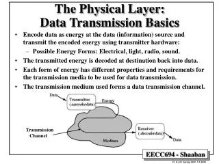
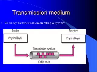
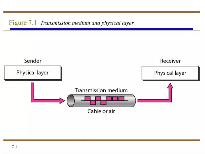
Figure 7.1 Transmission medium and physical layer. Figure 7.2 Classes of transmission media. Overview. Guided - wire Unguided - wireless Characteristics and quality determined by medium and signal For guided, the medium is more important

E N D
Overview • Guided - wire • Unguided - wireless • Characteristics and quality determined by medium and signal • For guided, the medium is more important • For unguided, the bandwidth produced by the antenna is more important • Key concerns are data rate and distance
Design Factors • Bandwidth • Higher bandwidth gives higher data rate • Transmission impairments • Attenuation • Interference • Number of receivers • In guided media • More receivers (multi-point) introduce more attenuation
Guided Transmission Media • Twisted Pair • Coaxial cable • Optical fiber
Twisted Pair - Applications • Most common medium • Telephone network • Between house and local exchange (subscriber loop) • Within buildings • To private branch exchange (PBX) • For local area networks (LAN) • 10Mbps or 100Mbps
Twisted Pair - Pros and Cons • Cheap • Easy to work with • Low data rate • Short range
Twisted Pair - Transmission Characteristics • Analog • Amplifiers every 5km to 6km • Digital • Use either analog or digital signals • repeater every 2km or 3km • Limited distance • Limited bandwidth (1MHz) • Limited data rate (100MHz) • Susceptible to interference and noise
Unshielded and Shielded TP • Unshielded Twisted Pair (UTP) • Ordinary telephone wire • Cheapest • Easiest to install • Suffers from external EM interference • Shielded Twisted Pair (STP) • Metal braid or sheathing that reduces interference • More expensive • Harder to handle (thick, heavy)
STP • The metal casing prevents the penetration of EM noise • It also can eliminate a phenomenon called Crosstalk, which is the undesired effect of one circuit (or channel) on another circuit (or channel) • This effect can be experienced during telephone conversations when one can hear other conversations in the background • Shielding each pair of twisted pair can eliminate most crosstalk • STP is more expensive than UTP but is less susceptible to noise
UTP Categories • Cat 1 • Basic Twisted pair cabling used in Telephone system • Fine for voice but inadequate for all but low-speed data communication • Cat 2 • The next higher grade, suitable for voice and for data transmission of up to 4Mbps
UTP Categories • Cat 3 • up to 16MHz • Voice grade found in most offices • Twist length of 7.5 cm to 10 cm • Now the standard cable for most telephone lines • Cat 4 • up to 20 MHz • Must have at least 3 twists per foot • Cat 5 • up to 100MHz • Commonly pre-installed in new office buildings • Twist length 0.6 cm to 0.85 cm
Near End Crosstalk • Coupling of signal from one pair to another • Coupling takes place when transmit signal entering the link couples back to receiving pair • i.e. near transmitted signal is picked up by near receiving pair
Coaxial Cable Applications • Most versatile medium • Television distribution • Ariel to TV • Cable TV • Long distance telephone transmission • Can carry 10,000 voice calls simultaneously • Being replaced by fiber optic • Short distance computer systems links • Local area networks
Coaxial Cable Connectors • Over the years, a no. of connectors have been designed for use with coaxial cable • Most common of the connectors is called “BARREL connector” because of its shape • Of the barrel connectors, the most popular is the Bayonet Network Connector (BNC) • BNC connector pushes on and locks into place with half turn • Other types of barrel connectors either screw together and so require more effort to install or push on w/o locking which is less secure
Coaxial Cable - Transmission Characteristics • Analog • Amplifiers every few km • Closer if higher frequency • Up to 500MHz • Digital • Repeater every 1km • Closer for higher data rates
Refraction • Light travels in a straight line as long as it is moving through a single uniform structure • If a ray of light traveling through one substance enters another (more or less dense) substance, its speed changes abruptly causing the ray to change direction, This phenomenon is called Refraction • When angle of incidence becomes greater than critical angle, reflection occurs • Light no longer passes into the less denser medium but is reflected back into the same medium • The Angle of Incidence (I) = Angle of Reflection ®
Optical Fiber • Optical fibers use Reflection to guide light through a channel • A glass or plastic CORE is surrounded by a CLADDING of less dense glass or plastic • The difference in the density of CORE and CLADDING is such that the beam of light moving through the core is reflected off the cladding • Information is encoded onto a beam of light as a series of ON-OFF flashes that represent 1 and 0 bits
Optical Fiber - Benefits • Greater capacity • Data rates of hundreds of Gbps • Smaller size & weight • Lower attenuation • Electromagnetic isolation • Greater repeater spacing • 10s of km at least
Optical Fiber - Applications • Long-haul trunks • Metropolitan trunks • Rural exchange trunks • Subscriber loops • LANs
Optical Fiber - Transmission Characteristics • Act as wave guide for 1014 to 1015 Hz • Portions of infrared and visible spectrum • Light Emitting Diode (LED) • Cheaper • Wider operating temp range • Last longer • Injection Laser Diode (ILD) • More efficient • Greater data rate • Wavelength Division Multiplexing
Multimode Step Index • Density of the CORE remains constant from the center to the edges • A beam of light moves through this constant density in a straight line until it reaches the interface of the core and the cladding • At the interface, there is an abrupt change to lower density, that alters the angle of the beam’s motion • Step Index Suddenness of this change • Some beams travel straight • Some strike the interface of core and cladding at an angle smaller than critical angle and penetrate cladding and are lost
Disadvantage of Multimode Step-Index Fiber • Each beams angle is equal to its angle of reflection • If I is small, R is small and the beam will require more bounces and it will take more time to reach the destination • If I is large, R is large and beam will reach destination quickly • In other words there is a difference is Path Lengths that results into a distortion at the receiver • This distortion limits the data rate and make Multimode Step index fiber inadequate for precise applications
Multimode Graded index • A grade index fiber is the one with varying densities • Density is highest at the center of the core and decreases gradually to its lowest at the edge • The signal is introduced at the center of the core • Beams at other angles moves through the series of constantly changing densities • Each density difference causes each beam to refract into a curve • Signal can be reconstructed with far greater precision as all the beams reach the receiver at almost the same time
Wireless Transmission • Unguided media • Transmission and reception via antenna • Directional • Focused beam • Careful alignment required • Omnidirectional • Signal spreads in all directions • Can be received by many antennae
Note Radio waves are used for multicast communications, such as radio and television, and paging systems.