Download
1 / 43
430 likes | 569 Views
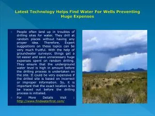
Water Wells for Yield and Health. By Michael L. Vaught EGIS PA 441 Northside Dr. Map Segment 6 Geographical provinces Types of aquifers Map Segment 11 capp.water.usgs.gov/gwa/gwa.htm. Ground Water Atlas of the United States.

E N D
Water Wells for Yield and Health By Michael L. Vaught EGIS PA 441 Northside Dr
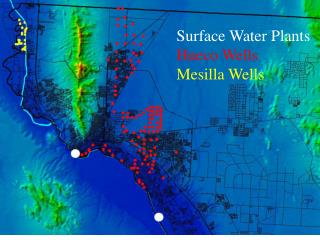
Map Segment 6 Geographical provinces Types of aquifers Map Segment 11 capp.water.usgs.gov/gwa/gwa.htm Ground Water Atlas of the United States
http://mapping.usgs.gov/mac/isb/pubs/booklets/usgsmaps/atlas.htmlhttp://mapping.usgs.gov/mac/isb/pubs/booklets/usgsmaps/atlas.html
Sedimentary, Metamorphic, and Igneous rocks. Hard to crystalline rock verses unconsolidated granular aquifers. Reference the Ground Water Atlas of the United States and the Geological Surveys Maps. Rock Type
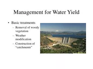
Water Wells for Yield • Depth • Diameter • Screens • Test yield
Geographic or Physiographic location Coastal Plain Piedmont Mountains Type of Well shallow or deep large or small diameter cased or “open hole” Depth & Diameter
Charles Daniel III, 1989, Geological Survey Water-Supply Paper 2341-A. Wells below 400’ Large stress release fractures 12” wells have 4 times yield of 6” wells Well Depth & DiameterHard to crystalline rock
Ralph Heath, 1983, Geological Survey Water-Supply Paper 2220. Depth depends on lowest zone tapped Aquifer Thickness & Composition Diameter has little effect on yield Limits pump size Well Depth & Diameterunconsolidated granular aquifers
4inch 6 8 10 12 Ratio of Yields by diameter
Well Screens • Sizes • Types of material
Required yield EPA 570/9-91-004 Homeowner per resident 50-75 gpd Campgrounds per camper 15 gpd Cottages seasonal per resident 50 gpd Restaurants per patron 7 - 10 gpd Test Yield
Codes and regulations. Well Capacity Domestic (not public, industrial, irrigation) Max continuous quantity for 1 hour Note static and pumping WL’s and GPM Test Yield
Static Level Pumping Level Drawdown Pumping Rate Pump Depth Recharge Rates Static Head Test YieldSpecific Capacity
Test YieldSpecific Capacity • 100GPM Withdrawal • 15’ • Static WL • 45’ • Pumping WL • 100gpm / (45-15)ft • = specific capacity of • 3.3 gpm/ft of drawdown • Specific Capacity of a newer well • 65 GPM Withdrawal • 15’ • Static WL • 65’ • Pumping WL • 65gpm / (65-15)ft • = specific capacity of • 1.3 gpm/ft of drawdown • Specific Capacity after 15 years
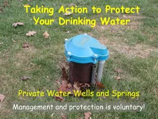
Casing Sealing the Annulus Wellhead Protection Air quality, drainage, and recharge Well Maintenance Flushing and circulation Well Health and Safety
Sealing the Annulus • Administrative codes and regulations • Minimum of 20’ • Bentonite, Cement, Concrete, Mixtures
Wellhead Protection • Wellhead Protection Guidebooks • WHPA Delineation Methods • Arbitrary fixed or calculated fixed radius method
Homeowner Campgrounds Cottages Non-community & Public Systems Well Maintenance
Pump Depth Exercise (water usage) Chlorination >200 ppm, 6 pH Record keeping Annual Testing for Bacteria Chlorination not recommended for coliform Well Maintenance
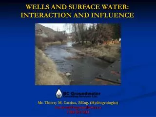
Pumping influences motion within the borehole column Pumping oxygenates the well water from the top down. Pumping draws shallow water downward. Pumping utilizes water from two sources; Well Storage and Well Flow. Set pump intake As Shallow As Possible (ASAP).
Stored water lies above the intake and the above the highest water zone Well Storage- Zone of the water column within or draining to the borehole that is both above the pump and above the most shallow production zone,( called the “ Storage Cell”). In Storage Type Wells the pumping water level continuously falls during the stress test. Well Storage
Flowing water moves between the production zones and the pump intake. Well Flow – Zone of the water column between the pump and any contributing production zone (called the “Flowing Cell”). In Flowing Type Wells the water level stabilizes during the stress test. Well Flow
Flowing type wells minimize the borehole Storage and maximize the Flowing Cells by the correct pumping depth. Flowing Cells remain cleaner because of the borehole turbulence and lack of enrichment. Flowing type wells = Long term reliability + controlled biofouling. Flowing type wells generally remain cleaner.
Typically Storage Cells become enriched and biofouled in the top of a water well. Storage type wells must be exercised regularly to flush biofilm and enriched water from the cell. Storage type wells = Short term maintenance + rapid biofouling. Storage type wells require periodic maintenance.
Excess Storage generates uncontrolled growth of naturally occuring biofilms within the well. Enrichment of the excess or recycled Storage accelerates biofouling from the top down. Set the pumping depth in a well based on Actual Maximum Demand. Set the pumping depth no more than twenty feet below the actual maximum demand level in the average Domestic size water well. Minimize Storage and Enlarge Flow Cells
Actual Maximum Demand Water Level – Depth to water within the well during one hour of continuous pumping while hooked to the system under simulated intense usage. Set the pumping depth no more than twenty feet below the actual maximum demand level in the average Domestic size water well. Set pump intake depth for actual maximum demand.
Recondition homeowners dirty wells by cleaning the biofouling and repositioning the pump (ASAP). Repairs eliminate shallow water. Borehole flow diverters change the Flowing Cells to eliminate turbidity. Rehabilitating biofouled wells means controlled biofilms.
Disinfecting Sealing Decommissioning Well Abandonment
Codes and Regulations Well owner Well contractor Pump installer Forms ______ Responsibility for Well Abandonment
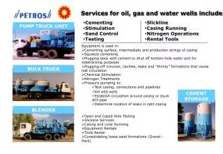
Large diameter, 18-36 inches Remove plumbing or obstructions Disinfect with calcium hypochlorite Remove well casing (3’ BGL) Fill with cement, concrete, bentonite, dry clay, natural material. Cap with 1’ cement plug extending 1’. Abandonment of Bored Wells
Gravel packed, screened, unconsolidated Remove or grout the casing Determine well depth Disinfect with calcium hypochlorite Fill with neat cement or Bentonite grout Cased open hole Same as above except……... Fill to 10’ below TOR or 5’ below CSG with cement, bentonite, sand, gravel, or cuttings. Fill to surface Abandonment of Drilled Wells
Well characterization is essential for sustained quantity and quality. It is the first step in configuring a water supply system for long-term yields of consistent water.” “Use-it-or-loose-it”, if the well is set up to supply more water than is routinely needed, maintenance must include maximum demand pumping either quarterly or monthly. “Private Water Systems Handbook” says; “A home water system must be able to supply the peak use rate continuously for one hour.” When the pump depth is set to maximize the well yield, the well may accumulate enriched water above the pump. Pump depth should be sufficient to allow only 10 to 20 feet of water above the pump during peak demand intervals. Adequate drawdown can stop oxygen enrichment and prevent biofouling. Summary
Web sites (yahoo search - water well drawdown) Books and Supplier Materials Professional Organizations American Groundwater Trust Groundwater Associations Water Systems Council Government EPA, USDA, USGS State Agencies Extension Service References