Download
1 / 22
320 likes | 755 Views
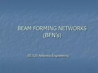
Beam Forming, Null Steering, and SDMA. Selecting the weights correctly allows transmitter (receiver) to steer the energy toward a receiver (or listen in the “direction” of a transmitter). This is called beam forming

E N D
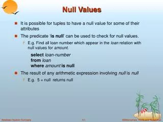
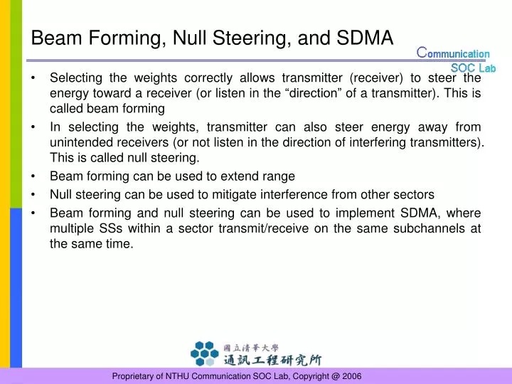
Beam Forming, Null Steering, and SDMA • Selecting the weights correctly allows transmitter (receiver) to steer the energy toward a receiver (or listen in the “direction” of a transmitter). This is called beam forming • In selecting the weights, transmitter can also steer energy away from unintended receivers (or not listen in the direction of interfering transmitters). This is called null steering. • Beam forming can be used to extend range • Null steering can be used to mitigate interference from other sectors • Beam forming and null steering can be used to implement SDMA, where multiple SSs within a sector transmit/receive on the same subchannels at the same time.
Beam Forming, Null Steering, and SDMA Beam Forming Null Steering SDMA Intended Subscriber Interfering Subscriber Subscriber Subscriber 2 Subscriber 1 Base Station Base Station Base Station
Channel Rejection • Measured by setting transmitting power 3dB larger than the minimum receiver sensitivity • Adjacent channel rejection • Conforming OFDMA signal • At least 11 dB power above than desired signal when 16-QAM-3/4 • At least 4 dB power above than desired signal when 64-QAM-2/3 • Non-adjacent rejection • Any channel other than adjacent channel or co-channel • At least 30 dB power above than desired signal when 16-QAM-3/4 • At least 23 dB power above than desired signal when 64-QAM-2/3 • BER < 10-6
AAS Support • Indicated by IEs in the DL and UL broadcast maps • AAS zone • A contiguous block of OFDMA symbols • Defined preamble structure • May contain an optional Diversity-Map scan zone (D-Msz) • Used only with FFT size larger than or equal to 512 • Used to transmit AAS-DLFP • AAS frame structure • Consists of subchannels • PUSC, FUSC, oFUSC permutation • Two highest numbered subchannels of DL frame may contain D-Msz • AMC permutation • The first and last numbered subchannels of AAS DL zone may contain D-Msz • A 2 bin by 3 symbol tile structure is used
AAS Support • In a given AMC subchannel, the beam pattern for all pilot and data subcarriers is the same • In a PUSC permutation, the SS assume the major group is beamformed • Channel may very slowly over the zone
Optional Diversity-Map scan • AAS-DLFP (Down Link Frame Prefix) • A robust transmission of the required BS parameters • Enable SS initial ranging • SS paging and access allocation • QPSK-1/2, 2 repetitions • Start with an AAS DL preamble • Specified the permutation of AAS UL Zone • May, but need not carry the same information • Supports the ability to transmit a compressed DL-MAP IE • Not randomized
AAS Network Entry • AAS-SS synchronizes frame timing and frequency by DL preamble • If decoding of broadcast map fails, search for AAS-DLFP over several permutations • The SS may receive DCD and UCD pointed from AAS-DLFP • Perform initial ranging using information from DCD and UCD, where the ranging interval is pointed by AAS-DLFP • Wait the ranging response • Normal operation
AAS Preambles • AAS preambles • Training information in both UL and DL AAS zone • Preceding all data allocation and AAS DLFP in AAS zone • Length is specified in the AAS_DL_IE and AAS-DLFP • Either time or frequency shifted • AAS DL preamble • Preamble length of AAS-DLFP is 1 symbol duration • In PUSC permutation, preamble length is 0 or 2 symbols • AAS UL preamble • The first Uplink_preamble_config symbols are reserved for UL AAS preambles • Inserted at the start of an UL data allocation by 3 symbol duration
AAS DL Preamble • Formed by concatenating the original preamble sequence • The length of basic preamble is Nused bits • BPSK modulation • DC carrier shall not be modulated • A subset of the basic preamble is used for burst
AAS UL Preamble • The basic preamble is the same as AAS DL preamble • A subset of the basic preamble is used for burst • Preamble power level when lower bound < C/N < upper bound otherwise
Preamble Shift • Time shift • Frequency shift K = [AAS_beam_index (mod 14)]*Nfft/14 for PUSC K = [AAS_beam_index (mod 14)]*Nfft/9 for AMC
STC Using 2 Antennas • STC may be used on the downlink to provide higher order diversity • 2 transmit antennas on BS • 1 reception antenna on SS • Similarly maximal ratio combining (MRC) • Transmit two different OFDMA symbol in the same time
STC Encoding • Antenna: A0,A1 • Channel vector: h0, h1 • Transmission complex symbol: s1, s2 • First transmission : A0 for s1, A1 for s2 • Second transmission : A0 for –s2*, A1 for s1* • The estimates benefit from second order diversity as in 1Tx-2Rx MRC scheme • May be used both in PUSC and FUSC configurations
STC2 in PUSC • The data allocation to cluster is slightly modified • STC encoding is done on each pair of symbols 2n, 2n+1 (n = 0,1,..)
STC2 in FUSC • Pilot for even symbol • A0: Variable set #0 and Constant set #0 • A1: Variable set #1 and Constant set #1 • Pilot for odd symbol • A0: Variable set #1 and Constant set #0 • A1: Variable set #0 and Constant set #1
Frequency Hopping Diversity Coding • The downlink preamble shall be transmitted for the duration of one OFDMA symbol from Antenna 0 • Transmission complex symbol: s1, s2 • Antenna: A0,A1 • A0: transmits mapped carriers for subchannel X(s1) onto subchannel X, and mapped carriers for subchannel X+1(s2) onto subchannel X+1 • A1: transmits mapped carriers for subchannel X(-s2*) onto subchannel X, and mapped carriers for subchannel X+1(s1*) onto subchannel X+1
STC Decoding • STC using 2 antennas • FHDC
Uplink Using STC (1/2) • A user-supporting transmission using STC configuration in the uplink • 2-transmit diversity data (STTD mode) • 2-transmit spatial multiplexing data (SM mode) • Mandatory tile structure shall be used with modification
Uplink Using STC (2/2) • STTD mode • The tiles shall be allocated to subchannels and the data subcarriers enumerated • data subcarriers shall be encoded in pairs • SM mode (subcarrier) • Two single transmit antenna SS’s can perform collaborative spatial multiplexing onto the same subcarrier • A single user having two antennas may do UL spatial multiplexing • Horizontal coding - 2 bursts concurrently • Vertical coding - 1 burst (2 slots) concurrently • SM mode (subchannel) • one SS should use the uplink tile with pattern-A while the other uses B • Two dual antenna SS • one SS should use the uplink tile with the pilot pattern A, B • one SS should use the uplink tile with the pilot pattern C, D
STC2 Enhancement • Using 4 antennas • 2 are used in order to transmit each symbol • 2 transmit the same signal with a complex multiplication • Antenna weights may be changed by BS with SS information using feedback channel (CQI channel) • No change of the estimation process


![[SDMA operation within 802.11]](https://cdn1.slideserve.com/3383357/sdma-operation-within-802-11-dt.jpg)