Download
1 / 34
340 likes | 417 Views
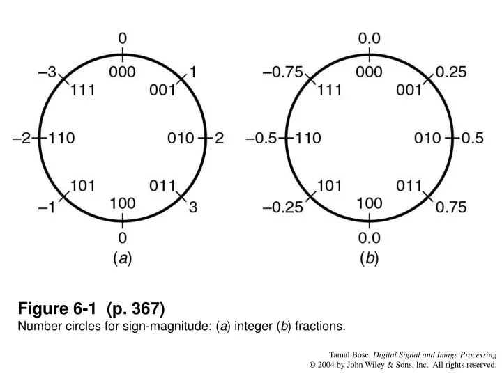
Figure 6-1 (p. 367) Number circles for sign-magnitude: ( a ) integer ( b ) fractions. Figure 6-2 (p. 368) Transfer characteristics for quantization with sign-magnitude numbers: (a) truncation; (b) rounding.

E N D
Figure 6-1 (p. 367)Number circles for sign-magnitude: (a) integer (b) fractions.
Figure 6-2 (p. 368)Transfer characteristics for quantization with sign-magnitude numbers: (a) truncation; (b) rounding
Figure 6-3 (p. 368)Number circles for two-s complement: (a) integers, (b) fractions.
Figure 6-4 (p. 369)Transfer characteristic for two’s complement truncation.
Figure 6-5 (p. 370)IEEE-754 format for floating point numbers.
Figure 6-6 (p. 373)Pole locations for a second-order Direct Form filter quantized with 4 bits.
Figure 6-7 (p. 374)Pole locations for a second-order Coupled-Form filter quantized with 4 bits.
Figure 6-8 (p. 375)Frequency response of unquantized Butterworth filter.
Figure 6-9 (p. 376)Frequency response of Direct Form filter quantized to 8 bits.
Figure 6-10 (p. 377)Frequency response of cascade-form filter quantized to 8 bits.
Figure 6-11 (p. 377)Zero locations for a linear phase FIR filter.
Figure 6-12 (p. 378) Implementation of a pair of complex conjugate poles and their reciprocals with quantization of coefficients. ^ represents coefficient quantization. This structure preserves the linear phase property.
Figure 6-13 (p. 379)Quantization noise model for a first-order filter.
Figure 6-14 (p. 380)Probability density function for noise sources: (a) sign-magnitude; (b) two’s complement truncation; (c) rounding.
Figure 6-15 (p. 382)Noise model for a second-order Direct Form II filter using a single-length accumulator.
Figure 6-18 (p. 387)Transfer characteristic of the sign-magnitude overflow operation.
Figure 6-19 (p. 387)Transfer characteristic of saturation overflow.
Figure 6-20 (p. 388)Transfer characteristic of the two’s complement overflow operation.
Figure 6-21 (p. 388)Transfer characteristic of the zeroing overflow operation.
Figure 6-22 (p. 390)Stability triangle for a second-order Direct Form filter. Shaded region: overflow stability region.
Figure 6-23 (p. 393)Stability realization of second-order filter with double pole at .
Figure 6-24 (p. 398)Quantization noise sources in a scaled second-order Direct Form II digital filter.
Figure 6-25 (p. 403)Roundoff stable region for a minimum norm filter.
Figure 6-26 (p. 404)Roundoff stable region for a Direct Form filter.
Figure 6-27 (p. 406)Stability region under magnitude truncation. (a) Coupled-Form filter, (b) Direct Form filter.
Figure 6-28 (p. 409)(a) Regions 1 and 2. Period-2 limit cycles can always be obtained. Region 3: Period-2 limit cycles may be present depending on initial conditions; Region 4: Region of global asymptotic stability; (b) Shaded region is the necessary and sufficient condition for the existence of period-1 limit cycles.
Figure 6-29 (p. 410) Stability region for a Coupled Form filter with TCQ given by sufficient condition.
Figure 6-30 (p. 411)Stability region for a Coupled Form filter with TCQ, obtained by an exhaustive search.
Figure 6-32 (p. 413)Stability region for a Coupled Form filter with TCQ implementation in a modified block form with a block size of 2.