Download
1 / 39
960 likes | 2.31k Views
Stress Transformation. 9.1-9.3 Plane Stress Stress Transformation in Plane Stress Principal Stresses & Maximum Shear Stress. Introduction. We have learned Axially In Torsion In bending These stresses act on cross sections of the members. Larger stresses can occur on inclined sections.

E N D
Stress Transformation 9.1-9.3 Plane Stress Stress Transformation in Plane Stress Principal Stresses & Maximum Shear Stress
Introduction • We have learned • Axially • In Torsion • In bending • These stresses act on cross sections of the members. • Larger stresses can occur on inclined sections.
Introduction • We will look at stress elements to analyze the state of stress produce by a single type of load or by a combination of loads. • From the stress element, we will derive the Transformation Equations • Give the stresses acting on the sides of an element oriented in a different direction.
Introduction • Stress elements: only one intrinsic state of stress exists at a point in a stressed body, regardless of the orientation of the element for that state of stress. • Two elements with different orientations at the same point in a body, the stress acting on the faces of the two elements are different, but represent the same state of stress • The stress at the point under consideration.
Introduction • Remember, stresses are not vectors. • Are represented like a vector with magnitude and direction • Do not combine with vector algebra • Stresses are much more complex quantities than vectors • Are called Tensors (like strain and I)
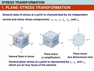
Plane Stress • Plane Stress – The state of stress when we analyzed bars in tension and compression, shafts in torsion, and beams in bending. • Consider a 3 dimensional stress element • Material is in plane stress in the xy plane • Only the x and y faces of the element are subjected to stresses • All stresses act parallel to the x and y axis
Plane Stress • Normal stress – • subscript identifies the face on which the stress acts • Sign Convention • Tension positive • compression negative
Plane Stress • Shear Stress - • Two subscripts • First denotes the face on which the stress acts • Second gives the direction on that face • Sign convention • Positive when acts on a positive face of an element in the positive direction of an axis (++) or (--) • Negative when acts on a positive face of an element in the negative direction of an axis (+-) or (-+)
Plane Stress • A 2-dimensional view can depict the relevant stress information, fig. 9.1c • Special cases • Uniaxial Stress • Pure shear • Biaxial stress
Stresses on Inclined Planes • First we know x, y, and xy, • Consider a new stress element • Located at the same point in the material as the original element, but is rotated about the z axis • x’ and y’ axis rotated through an angle
Stresses on Inclined Planes • The normal and shear stresses acting on they new element are: • Using the same subscript designations and sign conventions described. • Remembering equilibrium, we know that:
Stresses on Inclined Planes • The stresses in the x’y’ plane can be expressed in terms of the stresses on the xy element by using equilibrium. • Consider a wedge shaped element • Inclined face same as the x’ face of inclined element.
Stresses on Inclined Planes • Construct a FBD showing all the forces acting on the faces • The sectioned face is A. • Then the normal and shear forces can be represented on the FBD. • Summing forces in the x and y directions and remembering trig identities, we get:
Stresses on Inclined Planes • These are called the transformation equations for plane stress. • They transfer the stress component form one set of axes to another. • The state of stress remains the same. • Based only on equilibrium, do not depend on material properties or geometry • There are Strain Transformation equations that are based solely on the geometry of deformation.
Stresses on Inclined Planes • Special case simplifications • Uniaxial stress- y & Txy = 0 • Pure Shear - x &y = 0 • Biaxial stress - Txy = 0 • Transformation equations are simplified accordingly.
Principal & Maximum Shear Stresses • Since a structural member can fail due to excessive normal or shear stress, we need to know what the maximum normal and stresses are at a point. • We will determine the maximum and minimum stress planes for which maximum and minimum normal and shear stresses act.
Principal & Maximum Shear Stresses • Principal stresses – maximum and minimum normal stresses. • Occurs on planes where: • Applying to eq 9.1 we get: • p=the orientation of the principal planes • The planes on which the principal stresses act.
Principal & Maximum Shear Stresses • Two values of the angle 2p are obtained from the equation. • One value 0-180, other 180-360 • Therefore p has two values 0-90 & 90-180 • Values are called Principal Angles. • For one angle x is maximum, the other x is minimum. • Therefore: Principal stresses occur on mutually perpendicular planes.
Principal & Maximum Shear Stresses • We could find the principal stress by substituting this angle into the transformation equation and solving • Or we could derive general formulas for the principal stresses.
Principal Stresses • Consider the right triangle • Using the trig from the triangle and substituting into the transformation equation for normal stress, we get • Formula for principal stresses.
Shear Stresses on the Principal Planes • If we set the shear stress x’y’ equal to zero in the transformation equation and solve for 2, we get equation 9-4. • The angles to the planes of zero shear stress are the same as the angles to the principal planes Therefore:The shear stresses are zero on the principal planes
The Third Principal Stress • We looked only at the xy plane rotating about the z-axis. • Equations derived are in-plane principal stresses • BUT, stress element is 3D and has 3 principal stresses. • By Eigenvalue analysis it can be shown that z=0 when oriented on the principal plane.
Maximum In-Plane Shear Stress • Consider the maximum shear stress and the plane on which they act. • The shear stresses are given by the transformation equations. • Taking the derivative of x’y’ with respect to and setting it equal to zero we can derive equation 9-7
Maximum Shear Stress • The maximum negative shear stress min has the same magnitude but opposite sign. • The planes of maximum shear stress occur at 45 to the principal planes
Maximum Shear Stress • If we use equation 9-5, subtract 2 from 1, and compare with equation 9-7, we see that: • Maximum shear stress is equal to ½ the difference of the principal shear stress.
Average Normal Stress • The planes of maximum shear stress also contain normal stresses. • Normal stresses acting on the planes of maximum positive shear stress can be determined by substituting the expressions for the angle s into the equations for x’. • Result is Equation 9-8.
Important Points • The principal stresses are the max and min normal stress at a point • When the state of stress is represented by the principal stresses, no shear stress acts on the element • The state of stress at the point can also be represented in terms of max in-plane shear stress. In this case an average normal stress also acts on the element • The element in max in-plane shear stress is oriented 45° from the element in principal stresses.