Download
1 / 8
80 likes | 133 Views
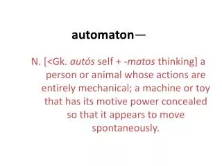
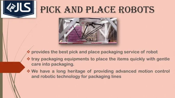
Manufacturing automaton is widely used in small and medium plants, however, automaton cooperating with other devices is an important aspect for achieving the fully autonomous system. This paper presents the Pick and Place Robot with Line Follower Function for manufacturing application. Model of pick and place robot which will be functioned following a specific line may benefit production to reduce the labor cost or maybe alternatives of the labors. This system has a line follower and pick and place function that is controlled by Andriod with Arduino. Lwin Lwin Htay | Nyan Phyo Aung | Mo Mo Myint Wai "Andriod Controlled Pick and Place Arm with Line Follower Automaton" Published in International Journal of Trend in Scientific Research and Development (ijtsrd), ISSN: 2456-6470, Volume-3 | Issue-5 , August 2019, URL: https://www.ijtsrd.com/papers/ijtsrd26407.pdf Paper URL: https://www.ijtsrd.com/engineering/electronics-and-communication-engineering/26407/andriod-controlled-pick-and-place-arm-with-line-follower-automaton/lwin-lwin-htay<br>

E N D
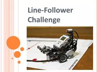
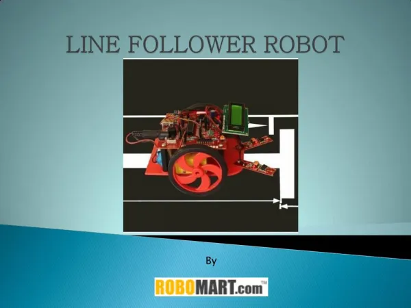
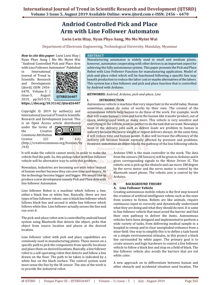
International Journal of Trend in Scientific Research and Development (IJTSRD) Volume 3 Issue 5, August 2019 Available Online: www.ijtsrd.com e-ISSN: 2456 – 6470 Andriod Controlled Pick and Place Arm with Line Follower Automaton Lwin Lwin Htay, Nyan Phyo Aung, Mo Mo Myint Wai Department of Electronic Engineering, Technological University, Mandalay, Myanmar How to cite this paper: Lwin Lwin Htay | Nyan Phyo Aung | Mo Mo Myint Wai "Andriod Controlled Pick and Place Arm with Line Follower Automaton" Published in International Journal of Trend in Scientific Research and Development (ijtsrd), ISSN: 2456- 6470, Volume-3 | Issue-5, August 2019, pp.565-572, https://doi.org/10.31142/ijtsrd26407 Copyright © 2019 by author(s) and International Journal of Trend in Scientific Research and Development Journal. This is an Open Access article distributed under the terms of the Creative Commons Attribution License (CC (http://creativecommons.org/licenses/by /4.0) It will make the vehicle cannot move. In order to make the vehicle find the path. So, this pickup robot with line follower vehicle will be alternative way to solve this problem. ABSTRACT Manufacturing automaton is widely used in small and medium plants, however, automaton cooperating with other devices is an important aspect for achieving the fully autonomous system. This paper presents the Pick and Place Robot with Line Follower Function for manufacturing application. Model of pick-and-place robot which will be functioned following a specific line may benefit production to reduce the labor cost or maybe alternatives of the labors. This system has a line follower and pick and place function that is controlled by Andriod with Arduino. KEYWORDS: Andriod; Arduino; pick-and-place; Line I. INTRODUCTION Autonomous vehicle is machine that very important in the world today. Human sometimes cannot do some of works by their own. The created of the autonomous vehicle help human to do these of the work. For example, work that will waste human’s time and harm the human like transfer product, out of space, underground work or many more. This vehicle is very sensitive and everything in the vehicle must be perfect to do the task that we want. Nowadays most of the delivery jobs such as deliver loads are problem to human in industry because the heavy weight or repeat delivers always. At the same time, it will reduce time and human power. It also will increase the efficiency of the delivery job because human normally affected by pressure and problems. However, sometimes an object blocks the pathway of the line following vehicle. IJTSRD26407 BY 4.0) Arduino UNO is the main controller in the work. The data from the sensors (IR Sensors) will be given to Arduino and it gives corresponding signals to the Motor Driver IC. The robotic arm is pick up the obstacle and can move 180 degree by the servo motor and the servo motor is control by the Bluetooth smart phone. The robotic arm is control by the Arduino. Nowadays, Industries are becoming use with robot instead of human worker because they can save time and money. As the technology become bigger and bigger. We would like to produce a new development namely Pick and Place Arm with line follower Automaton II. A.Line Follower Vehicle Creating autonomous mobile robots is the first step toward the creation of artificial intelligence robots such as the ones from science to fiction. Robots are like animals, require continuous input to correctly and dynamically understand what they are doing and what they should do next. It is same to line follower vehicle that must avoid the barrier and find their own pathway to deliver the items. Autonomous vehicles have been designed and implemented to perform a wide variety of tasks, from delivering medical sample in a hospital to sweep and to clear unexploded ordnance from a mine-field. One way to simplify this is to define a task based on a simple environmental stimulus, in this project a black line surrounded by white paper. The primary goal is to create sensors and logic hardware to control a line follower vehicle to follow a black line and stop on a field of black. The line follower vehicle also avoids the barriers that are not white color. BACKGROUND THEORY Line follower Robot is a machine which follows a line, either a black line or white line. Basically, there are two types of line follower robots: one is black line follower which follows black line and second is white line follower which follows white line. Line follower actually senses the line and run over it. The pick-and-place robot arm is controlled by android based system using Bluetooth that detects the object, picks that object from source location and places at the desired location. Line follower robot with pick and place capabilities are commonly used in manufacturing plants. These moves on a specific path to pick the components from specific locations and place them on desired locations. Basically, a line follower robot is a self-operating robot that detects and follow a line drawn on the floor. The path to be taken is indicated by a white line on the black surface. The control system used must sense the line by the IR sensor. The aim of the work is to provide the industrial robot. A new approach on to differentiate between human and other obstacle and accidental situation send location. The @ IJTSRD | Unique Paper ID – IJTSRD26407 | Volume – 3 | Issue – 5 | July - August 2019 Page 565
International Journal of Trend in Scientific Research and Development (IJTSRD) @ www.ijtsrd.com eISSN: 2456-6470 passive Infrared sensor is mainly used to detect human or animal. Arduino UNO is used in this project. [1] Designed a line follower robot to be able to follow a black line on the ground without getting off the line too much. The robot has two sensors installed underneath the front part of the body, and two DC motors drive wheels moving forward. A circuit inside takes the input signal from two sensors and controls the speed of wheels’ rotation. [2] B.A Remote Controlled “Pick and Place” A remote controlled Robotic Vehicle has been completed. A prototype was built and confirmed functional. This system would make it easier for man to unrivalled the risk of handling suspicious objects which could be hazardous in its present environment and workplace. Complex and complicated duties would be achieved faster and more accurately. [3] Robots have their historical past though they came into existences only in 1961 when Unimation Inc, a company founded in 1956 by American engineer Joseph Engelberger introduced the first servo-controlled industrial robots. Early development dating back to 500B.C shows that the Egyptians, Indians, the Chinese, and the Romans built many automatics puppets which imitate the movement of animals and birds. The Chinese built many amusing devices that depicted sequential motions. Also, the early men discovered many mechanisms and exhibited their innovation skill in building ships and introduced looms to weave. [4] The planet corporation in 1959 introduced a pick and place robot. In 1961, the first industrial robot was commercialized by Unimation Inc. Microprocessor technology was brought by INTEL in 1961. The real robot development process continued between 1968 and 1982 when various models of robots were developed by leading robot scientists in different universities, national laboratories and different industrial houses in the USA, Japan, France, UK, and other European countries. C.Self Sufficient Robotic Arm A self-sufficient robotic arm is fabricated by using components like micro-controllers and motors. This increases their speed of operation and reduces the complexity. It also brings about an increase in productivity which makes it easy to shift to hazardous materials. In the implementation process, the necessary components of structure ICs, blocks and power supply are all assembled on the PCB. The Robotic Arm is designed using the Microcontroller i.e. ATMEGA8 Micro-controller using Arduino programming. This process works on the principle of interfacing servos, Bluetooth module and mobile application. This task is achieved by using Arduino board. Bluetooth play an important role. The remote is fitted with mobile application and the servos are attached to the body of IV. IMPLEMENTATION OF THE PROPOSED SYSTEM There are two functions in the proposed system. The line follower and pick-place arm functions must be concerned. In general, there is two portions: hardware and software. The hardware portion must be solve two functions. The software portion can also solve these two functions. The main Arduino UNO controller is used to control two functions in hardware portions. From the block diagram of the proposed system, the overall circuit diagram of the system can be drawn. The overall of the system is as shown in figure 2. the robotic arm. The Bluetooth module is used for transparent wireless serial connection setup. Serial port Bluetooth module is fully qualified Bluetooth V2.0+EDR (Enhanced Data Rate) 3Mbps Modulation with complete 2.4GHz radio transceiver and baseband. It uses CSR Bluecore 04-External single chip Bluetooth system with CMOS technology and with AFH (Adaptive Frequency Hopping Feature). The Bluetooth module has to be connected with the Arduino physically by the Rx and Tx pins in both chips. But it does not matter whether the Bluetooth module pin in Tx and Rx must connect the Arduino pin Tx and Rx. It can also connect the PWN (Pulse width modulation) pin in Arduino. This Bluetooth module also must be connected with the mobile phone that has the Android application and in this case the application will send data through the Bluetooth to the Arduino. Hence the servo is controlled with Bluetooth android application [5]. At present, the main interest is to protect nuclear workers in highly contaminated areas or hostile environments, robots can be used in nuclear power plants to reduce human exposure not only to radiation, but also to hot, humid and oxygen-deficient atmosphere researchers in the field of robotics are proposing a great variety of robot configurations and functional capabilities to be used in nuclear power plants. Wheeled robots and tracked vehicles are the common configurations for mobile robots. [6]. The robotic arm was designed with four degrees of freedom and programmed to accomplish accurately simple light material lifting task to assist in the production line in any industry. 3D printing method is used in this project to fabricate the components of the robotic arm. Therefore, it provided more precise dimensions and huge time and cost- saving in fabrication. The robotic arm is equipped with 4 servo motors to link the parts and bring arm movement. Arduino, an open-source computer hardware and software is applied to control the robotic arm by driving servo motors to be capable to modify the position. [7]. The performance of the micro-robotic system has the potential to have an important role in such applications with reference to the transportation, handling and storage of micro objects. For that, has developed an automated system consisting of multiple drilling micro-robots. [8] III. THE PROPOSED SYSTEM The proposed system is as shown in figure 1. In this system, the robot has line following and Pick-up functions to provide automation. The one controller is used to control these functions. Power is supplied by 7.4 dc source to parts. Left and right dc motor of robot is driven by UNO using motor driver. Ir sensors is used to guide the directions of robot by line. Pick and Place arm is controlled by two servo motors that is control form phone via Bluetooth module with UNO. @ IJTSRD | Unique Paper ID – IJTSRD26407 | Volume – 3 | Issue – 5 | July - August 2019 Page 566
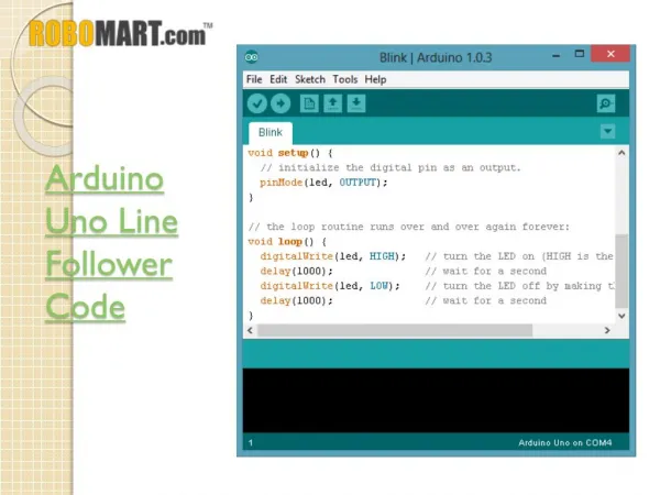
International Journal of Trend in Scientific Research and Development (IJTSRD) @ www.ijtsrd.com eISSN: 2456-6470 7.4V Battery For line follower Arduino UNO Motor Driver DC Motors (Left&Right) IR sensors For Pickup Bluetooth Module Servo Motors Figure1. the Block Diagram of Andriod Controlled Pick and Place Arm with Line Follower Automaton Gear Motor Gear Motor Motor Driver 12V GND 5V IN1 IN2 IN3 IN4 TOREST AREF REST GND 3.3V 13 5V 12 GND ~11 GND ~10 Vin ~ 9 A1 8 A2 7 A3 ~6 A4 ~ 5 A5 4 ~3 2 Rx1 Tx 0 Servo Motor Out 5V GND OUT 5V GND Servo Motor Power supply OUT 5V GND Servo Motor 7.4V battery OUT 5V GND Servo Motor GND + OUT EN GND + OUT EN Rx Tx GND Vcc module HC-06 Bluetooth IR Sensor IR Sensor Figure2. The Overall Circuit Diagram of the Proposed System A.Arduino In the hardware portion, the main controller unit is Arduino. It is an open source microcontroller which can be easily programmed, erased and reprogrammed at any instant of time. Based on simple microcontroller boards, it is an open source computing platform that is used for constructing and programming electronic devices. It is also capable of acting as a mini computer just like other microcontrollers by taking inputs and controlling the outputs for a variety of electronics devices. It is also capable of receiving and sending information over the internet with the help of various Arduino shields, which are discussed in this paper. Arduino uses a hardware known as the Arduino development board and software for developing the code known as the Arduino IDE (Integrated Development Environment). Built up with the 8-bit Atmel AVR microcontroller's that are manufactured by Atmel or a 32-bit Atmel ARM, these microcontrollers can be programmed easily using the C or C++ language in the Arduino IDE.[9] Figure3 Arduino Uno Board B.IR Obstacle Avoidance Sensor Module An Obstacle Avoidance Sensor (as shown below) uses infrared reflection principle to detect obstacles. When there @ IJTSRD | Unique Paper ID – IJTSRD26407 | Volume – 3 | Issue – 5 | July - August 2019 Page 567
International Journal of Trend in Scientific Research and Development (IJTSRD) @ www.ijtsrd.com eISSN: 2456-6470 is no object in front, infrared-receiver cannot receive signals; when there is an object in front, it will block and reflect infrared light, then infrared-receiver can receive signals. An obstacle avoidance sensor mainly consists of an infrared- transmitter, an infrared-receiver and a potentiometer. According to the reflecting character of an object, if there is no obstacle, emitted infrared ray will weaken with the propagation distance and finally disappear. If there is an obstacle, when infrared ray encounters an obstacle, it will be reflected back to the infrared-receiver. Then the infrared- receiver detects this signal and confirms an obstacle exists in front.The infrared sensor has two LEDs, IR Transmitters and IR receivers also called photo diodes. They are used for sending and receiving light.IR sensor has 4 pins; Gnd, Vcc, Vout, En. It operates at 5V DC. The figure 4 show the photo of IR sensor module. The line function can be worked with these ir sensor. In this system the two ir sensor module is used to guide the movement of robot that is followed by line. Figure6. L298 Driver Module E. Servo Motor The servo motor can rotate 180 degree and can use as moveable joint. The servo motor is usually a simple DC motor controlled for specific angular rotation with the help of additional servomechanism (a typical closed-loop feedback control system). Now day’s servo system has large industrial applications. Servo motor application are also commonly seen in remote-controlled toy cars for controlling the direction of motion, and it is also very widely used as the motor which moves the tray of a CD or DVD player. The main reason behind using a servo is that it provides angular precision, i.e. it will only rotate as much we want and then stop and wait for next signal to take further action. The servo motor is unlike a standard electric motor which starts turning as when we apply power to it, and the rotation continues until we switch off the power. It cannot be controlled the rotational progress of electrical motor, but we can only control the speed of rotation and can turn it ON and OFF. In this system, there is pick and place arm. The movement of these arm is controlled by two servo motor. And the gripper function of the arm is also controlled by the servo motor. These servo motor does not required the driver module. Because these are small and compatible with Arduino 5v voltage level. So Arduino generate the PWM pluses to drive these servo. The figure 7 shows the servomotor that used in this system. The arm have is driven by four servomotors: base, shoulder, elbow, wrist and has a gripper as end-effectors. The gripper has fingers grasping and manipulation of objects. Figure4. IR Obstacle Avoidance Sensor Module C.DC Motor A DC motor is any of a class of electrical machines that converts direct current electrical power into mechanical power. It is working between 3V to 12V. The figure 5 shows the photo of DC motor that used in the system. The motors are used to move the robot. And they are driven by Uno with L298 Diver module. The part number of the motor is OL- MOTOR-TT . Figure5 DC motor with wheel D.Motor Drive Module Arduino Uno can’t drive the dc motor directly. The current and voltage levels are not match with controller and dc motors. So motor driver is needed to drive the motor by Uno. The Uno generate only the pulse to drive the motor via driver. The major motor drive components for DC motors are: a controller, a motor driver IC or a motor driver circuit, the desired DC motor being used, power supply unit and the necessary connections to the motor. There is circuit that completer function of the driver for dc motor. That is called L298 motor drive module. In this system, there is one L2958 module is used. The photo of L298 module is as shown in figure 6. Motor Driver is a H-Bridge which can rotate motor in both clockwise and anti-clockwise direction. L293D is a typical example of motor driver. It has dual H-Bridge means, can drive two motors at once and it can provide maximum 600 mA current to each channel. So, the L293D motor is used for line follower robot. Figure7. The Servo Motor F.Power Supply The system must be required the DC power. In this system has two functions that are line follower and arm. The minimum required voltage is 7 V DC. The requirements can be solved by using two rechargeable 3.7V Li-ion (18650) battery. This battery can be produced about 7.4 v @2A. So it can be solve the power requirement of the system. An 18650 battery is a cell that’s 18mm x 65mm in size. The name, 18650, refers exclusively to the size of the lithium-ion battery cell, but there can be minor variations even here. The 18650 has become the new gold standard for replaceable and rechargeable batteries. The 18650 is a type of rechargeable lithium-ion battery. Lithium-ion batteries have revolutionized portable devices. They’re in everything, from our smartphones and cameras to baby monitors, fitness gadgets, and flashlights. @ IJTSRD | Unique Paper ID – IJTSRD26407 | Volume – 3 | Issue – 5 | July - August 2019 Page 568
International Journal of Trend in Scientific Research and Development (IJTSRD) @ www.ijtsrd.com eISSN: 2456-6470 Rechargeable batteries provide clean and reliable power. Figure 8 show the photo of rechargeable 3.7V Li-ion battery. are two types of Bluetooth module. HC-05 Bluetooth module and HC-06 module. HC-05 Bluetooth Module is an easy to use Bluetooth SPP (Serial Port Protocol) module, designed for transparent wireless serial connection setup. Its communication is via serial communication which makes an easy way to interface with controller or PC. HC-05 Bluetooth module provides switching mode between master and slave mode which means it able to use neither receiving nor transmitting data. Figure 10 shows the diagram of HC-05 Bluetooth module. Figure8. Rechargeable 3.7V Li-Ion Battery G.Bluetooth Module Bluetooth is a wireless technology standard for exchanging data over short distance. It is a standard wire-replacement communication protocol primary designed for low-power consumption, with a short range based on low-cost transceiver microchips in each device. Because the devices are use a radio (broadcast) communication system, they do not have to be in visual line of sight of each other, and however a quasi-optical wireless path must be viable. There The Bluetooth module is used to control the servo motors of the pick and place and gripper of arm. Pick and place arm can be controlled by mobile phone because these module is used in the system. Another portion of the system is implementation of the system. The software must develop for two functions. Figure 11 show the flow chart of line follower function of robot. The IR sensor transmit and receive light and send the data signal to the Arduino. The Arduino receiving data is send to the motor driver and the motor turn on. If sensor 1(left One) is in black and sensor 2(right one) is in white the robot car will turn left and the left motor will turn off. If sensor 1(left One) is in white and sensor 2(right one) is in black the robot car will turn right and the right motor will turn off. If both sensors; sensor 1(left One) and sensor 2(right one) are in black both left and right motors stop. Figure 10 HC-05 Bluetooth Module Start YES Does only left sensor see black? Turn left (left motor off) No YES Does only right sensor see black? Turn right (Right motor off) No YES Both left & right motor stop Do both sensor see black? No Both left & Right motor go forward Figure11. Flow Chart Of Line Follower Function Of Robot The function of pick and place arm is controlled by mobile phone via Bluetooth. these function of the flow chart is as shown in figure 12. Arduino receives data through the Bluetooth via serial communication. The Arduino check the data if arrive or not from the mobile phone with the instruction ‘if (Serial. Available ( ))’. If the conduction is true, the data is stored and the robot car is controlled as the input command numbers. @ IJTSRD | Unique Paper ID – IJTSRD26407 | Volume – 3 | Issue – 5 | July - August 2019 Page 569
International Journal of Trend in Scientific Research and Development (IJTSRD) @ www.ijtsrd.com eISSN: 2456-6470 The number ‘1’ is used for the base servo rotate. The number ‘2’ is used for shoulder servo rotate. The number ‘3’ is used for wrist servo rotate and the number ‘4’ is used for the gripper servo rotate. If none of these servos is not rotate check the serial. Read and reconnect. Start Variable Declation Serial Available ( ); No Reconnect State= serial .read YES YES Base servo rotate State = “1” No YES Shoulder servo rotate State = “2” No YES Wrist servo rotate State = “3” No YES Gripper servo rotate State = “4” No Figure12. The Function of Pick and Pace Arm Of The System EXPERIMENTAL RESULTS AND CONCLUSION implementation of software and hardware implementation, the system is tested in real environment. The figure 13 shows the complete model of the system. The construction is complete, the step by step testing is started when the system is completed. The line follower function of the system is a mobile machine that can detect and follow the line drawn on the floor. Generally, the path is predefined and can be either visible like a black line on a white surface with a high contrasted color or it can be invisible like a magnetic field. Definitely, this kind of robot should sense the line with its infrared ray (IR) sensors that installed under the robot. After that, the data is transmitted to the processor by specific transition buses. Hence, the processor is going to decide the proper commends and then it sends them to the driver and thus the path will be followed by the line follower robot. By detecting the IR radiation the line follower robot can be moved to left and right. In line follower two IR sensors are used for the process namely left sensor and right sensor. Line follower function of robot will follow the black line that is when the left sensor fall on the black surface the right motor will drive and when the right sensor fall on the black V. After surface the left motor will drive. Moreover when the left sensor and right sensor fall on the black surface on the same time both the left and right motors will stop. The test and result for the line follower function of the robot is as shown figures 14 and 15. Figure13. The Complete Model of The System @ IJTSRD | Unique Paper ID – IJTSRD26407 | Volume – 3 | Issue – 5 | July - August 2019 Page 570
International Journal of Trend in Scientific Research and Development (IJTSRD) @ www.ijtsrd.com eISSN: 2456-6470 Figure14. Test And Result of Two IR Sensor Fall On White Surface Figure16. Test of the pick and place arm of the system Figure15. Test and Result of Two IR Sensor Fall On Black Surface The pick and place arm is built with four servo motors; base servo, shoulder servo, wrist servo and gripper servo. The output base servo is connected to the Arduino digital pin 3, the output shoulder servo is connected to Arduino digital pin 5, the output wrist servo is connected to Arduino digital pin 6 and the gripper servo is connected to Arduino digital pin 9. These four servo motors are controlled by the Bluetooth module with Bluetooth smart phone. The Bluetooth module Tx and Rx pin is connected to the Arduino digital pin 10 and 11. The pick and place arm can move 180 degree by the servo motor and the servo motors are controlled by smart phone via Bluetooth. The control signal is sensed by Uno via Bluetooth. So the arm can be pick and place with movement. By using robotic arm, small object can pick and place from one place to desire location. Test and result of the function of pick and place arm is as shown in figure. And the android command view of the pick and place function of system is as shown in figure 16 and 17. In figure 17, there four color which represent the four servo motors of the arm. Figure17. Andriod application of the arm command VI. This work has been described the prototype model design of Android Controlled Pick and Place Arm with Line Follower Automaton . The system mainly focus on the industrial application. In manufacturing plant, the robot must be moved by path that can detect and follow the line drawn on the floor. Generally, the path is predefined and can be either visible like a black line on a white surface with a high contrasted color or it can be invisible like a magnetic field. . And a robotic arm is implemented using Arduino and Andriod to pick and place objects more safely without incurring much damage. The robotic arm used here contain a soft catching gripper which safely handle the object. Acknowledgment (Heading 5) This work is done with my candidate, Mg Kyaw Myo Tun and Ma Shan Ei Su. The authors would like to thank other member of this publication. CONCLUSION @ IJTSRD | Unique Paper ID – IJTSRD26407 | Volume – 3 | Issue – 5 | July - August 2019 Page 571
International Journal of Trend in Scientific Research and Development (IJTSRD) @ www.ijtsrd.com eISSN: 2456-6470 [6]Goldy Katal, Saahil Gupta, Shitij Kakkar, “Design And Operation of Synchronized Robotic Arm,” IJRET: International Journal of Research in Engineering and Technology E-ISSN: 2319-1163 | P-ISSN: 2321-7308. Reference [1]Khaled and Samial, “Proposed A New Approach On To Differentiate Between Human And Other Obstacle And Accidental Situation Send Location,”2013. [2]Jaseung Ku, “The Theory of Line Flower Robot,” 2005. [7]Matt Blackmore, Jacob Furniss and Shaun Ochsner, “5 DOF Robotic Arm”, ECE 478/578 Embedded Robotics, Fall 2009 [3]B. O. Omijeh, “A Remote Controlled “Pick And Place” Robotic Vehicle,” International Journal of Engineering research And development, Vol. 10, No. 5, 2014.www.ijerd.com [8]Sajid Ghuffar, Javaid Iqbal, Usman Mehmood And Muhammad Zubair, “Design and Fabrication of a Programmable 5-DOF Autonomous Robotic Arm,” 6th WSEAS Int. Conf. on Systems Theory & Scientific Computation, Elounda, Greece, August 21-23, 2006 [4]Engelberger, “introduce the first servo control industrial robot, ”1961. [5]A. N. W. Q, K. L. Voon, M. A. Ismail, N. Mustaffa, M. H. Ismail, “Design and Development of a Mechanism of Robotic Arm for Lifting,” 2nd Integrated Design Project Conference (IDPC), 2015. [9]Nyan Phyo Aung, Mo Mo Myint Wai, Lwin Lwin Htay and Kyawt Kyawt San, “Web Server Based Solar Parameters Monitoring using Arduino,” International Journal of Trend in Scientific Research and Development (IJTSRD), Vol 3, No. 5, 2019.pp296 @ IJTSRD | Unique Paper ID – IJTSRD26407 | Volume – 3 | Issue – 5 | July - August 2019 Page 572