Download
1 / 29
300 likes | 604 Views
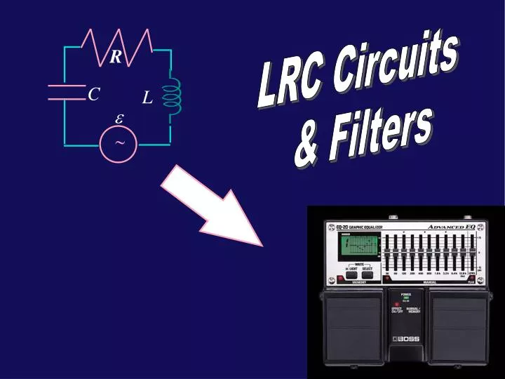
R. C. L. e. ~. LRC Circuits & Filters. RLC circuits with a sinusoidal drive Phase difference between current & voltage for Resistors, Capacitors, and Inductors. Reactance Phasors Application to frequency filters (high-, low-pass). Today. R. e o sin w t. +. +. C. L. -. -.

E N D
R C L e ~ LRC Circuits & Filters
RLC circuits with a sinusoidal drive Phase difference between current & voltage for Resistors, Capacitors, and Inductors. Reactance Phasors Application to frequency filters (high-, low-pass) Today...
R eosinwt + + C L - - • However, the resistance of any real inductor will cause oscillations to damp out,unless we can supply energy at the rate the resistor dissipates it! How? A sinusoidally varying emf (AC generator) will sustain sinusoidal current oscillations! Generic problem: we are given an “ac voltage source” “driving” a circuit ~ • Last time we discovered that an LC circuit was a natural oscillator: Driven LRC circuits • Very useful → TV, radio, computer clocks, … We need to find the current that flows: I(t)=Iosin(w t-f) It is also sinusoidal at the same frequency, w possibly with some “phase” angle relative to the voltage source
~ • Our goal is to understand how an AC LRC circuit works. • Physical picture of each object: • Source: produces an oscillating voltage (supplies whatever current the rest of the circuit “requires”) • Resistor: causes a voltage drop when a current flows through. As soon as the voltage changes, so does the currentalways in phase. • Capacitor: resists change in charge Q resists change in voltage . voltage across capacitor lags behind (90˚) the current (charge leaving & entering the plates). • Inductor: resists change in magnetic flux resists change in current. current always lags voltage (90˚). Preview
We could solve this equation with tons of algebra involvingsin(w t)andcos(w t); or with simple complex algebra. We will do neither, but start by considering simple circuits with one element (R, C, or L) in addition to the driving emf. R C L e ~ • Procedure: start with loop equation AC CircuitsSeries LRC • Statement of problem: • Given e = emsinw t,findI(t). • Everything else will follow.
R only: Loop eqn gives: R Þ I R e Voltage across R in phase with current through R ~ Note: this is always, always, true in LRC circuit, always… I V R R 0 0 0 0 t t eR Circuit But voltage across R is not always in phase with source!
Voltage acrossClags currentthroughCby one-quarter cycle (90°). C I e C ~ Is this always true? YES! IC VC 0 0 t 0 t 0 • Now considerC only:Loop eqn gives: eC Circuit Þ Þ
Voltage across L leads currentthrough L by one-quarter cycle (90°). L e ~ IL VL 0 0 Yes, yes, but how to remember? 0 0 t t • Now consider L: Loop eqn gives: eL Circuit I Þ L Þ
VL leads IL VC lags IC …we’ll see about that Introducing... ELI the ICE man Hi kids, I’m Eli and I’ll help you learn physics !
LRC Circuit Given: Assume solution for current: I(t) = Im sin( t- ) R C L e ~ • Note that in all cases , though there may be a phase shift: XL XC reactance Summary thus far…
You can think of it as a frequency-dependent resistance. What is reactance? For high ω, χC~0 - Capacitor looks like a wire (“short”) For low ω, χC∞ - Capacitor looks like a break For low ω, χL~0 - Inductor looks like a wire (“short”) For high ω, χL∞ - Inductor looks like a break (inductors resist change in current)
, Voutpulled to ground , no current flows no voltage drop across R Vout~ ε Vout Consider the AC circuit shown. For very high frequencies, is Vout big or small? ε Filter Example #1 ~ Recall: capacitor resists change in voltage. High frequency more change smaller reactance smaller VC Low frequency capacitor has time to charge up larger VC What is ω0? Use dimensional analysis. So, this is a circuit that only passes low frequencies: “low-pass” filter Bass knob on radio
e R ~ w C (c) (b)w large (a)w small Lecture 19, Act 1 • A driven RC circuit is connected as shown. • For what frequenciesw of the voltage source is the current through the resistor largest?
Vout Vout Vout ~ ~ ~ ω=0 No current Vout ≈ 0 ω=∞ Capacitor ~ wire Vout ≈ ε a. More Filters High- pass filter b. ω= ∞ No current Vout ≈ 0 ω= 0 Inductor ~ wire Vout ≈ ε Low- pass filter c. ω= 0 No current because of capacitor ω= ∞ No current because of inductor (Conceptual sketch only) Band- pass filter
R C L e ~ • Our goal is to calculate the voltages • across the various elements, and also • the current flowing through the circuit. • If these were just three resistors in • series, we could calculate the net resistance • simply by adding the individual resistances. • Because current and voltage are 90° out of phase for the capacitor and the inductor, a straight sum does not work (unless you use complex numbers, which we don’t in P212). • Instead we use “phasors”, a geometric way to visualize an oscillating function (avoiding nasty trig. or complex numbers). • A phasor is a rotating “vector” whose magnitude is the maximum value of a quantity (e.g., V or I). • The instaneous value is the projection on the y-axis. • The phasor rotates at the drive frequency w. (Appendix) AC Circuits, Quantitative
R C L e ~ Phasors Problem: Given Vdrive= εm sin(ωt), find VR, VL, VC, iR, iL, iC Strategy: We will use Kirchhoff’s voltage law that the (phasor) sum of the voltages VR, VC, and VL must equal Vdrive.
R C L e ~ VR, iRR Problem: Given Vdrive= εm sin(ωt), find VR, VL, VC, iR, iL, iC Phasors, cont. • Draw VR phasor along x-axis (this direction is chosen for convenience). Note that since VR = iRR, this is also the direction of the current phasor iR. Because of Kirchhoff’s current law, iL= iC= iR≡i (i.e., the same current flows through each element).
R C L e ~ VL = i XL VR = i R Phasors, cont. Problem: Given Vdrive= εm sin(ωt), find VR, VL, VC, iR, iL, iC • Next draw the phasor for VL. Since the inductor current iL always lags VL draw VL 90˚ further counterclockwise. The length of the VL phasor is iLXL = iwL
VL = i XL R VR = i R C L VC = i XC e ~ Phasors, cont. Problem: Given Vdrive= εm sin(ωt), find VR, VL, VC, iR, iL, iC • The capacitor voltage VC always lags iC draw VC 90˚ further clockwise. The length of the VC phasor is • iCXC = i /wC The lengths of the phasors depend onR,L,C, andω. The relative orientation of theVR,VL, andVCphasors is always the way we have drawn it. Memorize it!
R C L e ~ VL εm VR VC Phasors, cont. Problem: Given Vdrive= εm sin(ωt), find VR, VL, VC, iR, iL, iC • The phasors for VR,VL, and VC are added like vectors to give the drive voltage VR+VL+VC= εm : • From this diagram we can now easily calculate quantities of interest, like the net current i, the maximum voltage across any of the elements, and the phasebetween the current the drive voltage (and thus the power).
A series RC circuit is driven by emfe =e m sinw t.Which of the following could be an appropriate phasor diagram? ~ 2B 2A VL εm VR VC Lecture 19, Act 2 εm VC VR VR VC εm (a) (b) (c) For this circuit which of the following is true? • The drive voltage is in phase with the current. • The drive voltage lags the current. • The drive voltage leads the current.
C e m sinw t ~ R RC Circuit, quantitative: VR = iR f VC = iXC εm
C Vout ~ e R Note: this is ω, RC Circuit, cont. Ex.: C = 1 μF, R = 1Ω High-pass filter
where . . . Im XL R εm C L e ImR ~ Im XC Im XC Im XL εm f ImR LRC Circuits, quantitative Þ The phasor diagram gives us graphical solutions forfandIm: ß
Reactances ~ frequency-dependent resistance Capacitors look like wires for high frequencies look like breaks for low frequencies Voltage lags current by 90˚ Inductors look like breaks for high frequencies look like wires for low frequencies Current lags voltage by 90˚ Filters (low-pass, high-pass, band-pass) LRC Circuit Apply KVL using phasors Im XL εm ImR Im XC Summary f
4 Ex. Source = y-component of the V-phasor ωt=0 ωt=90˚ V=εm V=0 y y 3 1 2 w ωt=45˚ ωt=270˚ x V=-εm • A phasor is a “vector” whose magnitude is the maximum value of a quantity (e.g., V) and which rotates counterclockwise in a 2-d plane with angular velocity w. Recall uniform circular motion: Appendix: Phasors The projections of r (on the vertical y axis) execute sinusoidal oscillation.
The phasor picture corresponds to a snapshot at some time t. The projections of the phasors along the vertical axis are the actual values of the voltages at the given time. One can draw the phasors at different times, simply by rotating the entire diagram. With this understanding, other questions can be easily answered… When the current through the circuit is maximum, what is the potential difference across the inductor? a) VL = 0 b) VL = VLmax/2 c) VL = VLmax When the capacitor is fully charged, what is the magnitude of the voltage across the inductor? a) VL = 0 b) VL = VLmax/2 c) VL = VLmax
Explanation: Charge on C = max VC Current = max VR VR VC VL VL • Since the current and VL are 90 degrees out of phase, when the current is at a maximum, VL will be at 0. When the capacitor is fully charged, the current through the circuit will be 0, and the magnitude of L will be at a maximum. • VL will actually be at a minimum because VC and VL are 180 degrees out of phase.