Download
1 / 26
260 likes | 328 Views
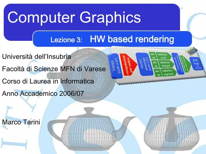
Lezione 3: HW based rendering. Università dell’Insubria Facoltà di Scienze MFN di Varese Corso di Laurea in Informatica Anno Accademico 200 6 /0 7. Computer Graphics. Marco Tarini. Riassunto puntate precedenti 1/3. Computer Graphics ( CG )... in particolare:

E N D
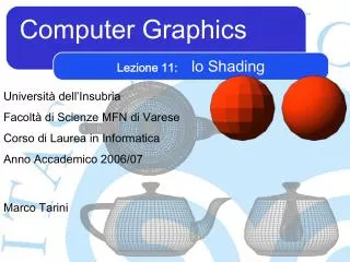
Lezione 3:HW based rendering Università dell’Insubria Facoltà di Scienze MFN di Varese Corso di Laurea in Informatica Anno Accademico 2006/07 Computer Graphics Marco Tarini
Riassunto puntate precedenti 1/3 • Computer Graphics ( CG )... • in particolare: • hardware-supported real-time rendering • detto anche "HW accelerated rendering" • hardware dedicato al rendeing GPU – Graphic Processing unitvs CPU – Central Processing Unit M a r c o T a r i n i ‧ C o m p u t e r G r a p h i c s‧ 2 0 0 6 / 0 7 ‧ U n i v e r s i t à d e l l ’ I n s u b r i a - 2
Riassunto puntate precedenti 2/3 • RENDERING PARADIGM: • (Triangle-) Rasterization Based • detto anche: • Transform and Lighting (T&L) • Che si usino solo le seguenti primitive di rendering :triangoli,segmenti,punti(o al limitequads, con diagonal split) • Raytracing • Rasterization based • Image based (per es. light filed) • Radiosity • Point-splatting • ... M a r c o T a r i n i ‧ C o m p u t e r G r a p h i c s‧ 2 0 0 6 / 0 7 ‧ U n i v e r s i t à d e l l ’ I n s u b r i a - 3
Riassunto puntate precedenti 3/3 "al volo" Quads r e n d e r i n g Campi d'altezza Forme geo. di base Triangoli Superfici parametriche n-agoni Dati Volumetrici Superfici implicite Nuvole di punti M a r c o T a r i n i ‧ C o m p u t e r G r a p h i c s‧ 2 0 0 6 / 0 7 ‧ U n i v e r s i t à d e l l ’ I n s u b r i a - 4
Transform & Lighting Transform & Lighting Punti 3D screenbuffer Segmenti 3D Triangoli 3D video scheda grafica M a r c o T a r i n i ‧ C o m p u t e r G r a p h i c s‧ 2 0 0 6 / 0 7 ‧ U n i v e r s i t à d e l l ’ I n s u b r i a - 5
Transform & Lighting... • Transform: • trasformazioni di sistemi di coordinate • scopo: portare la scena davanti all'obiettivo della nostra macchina fotografica (virtaule) • piazzare i triangoli visibili sullo schermo • Lighting: • illuminazione • (in senso generale) • scopo: calcolare il colore finale di ogni parte della scena • risultante da • le sue caratteristiche ottiche • l'ambiente di illuminazione M a r c o T a r i n i ‧ C o m p u t e r G r a p h i c s‧ 2 0 0 6 / 0 7 ‧ U n i v e r s i t à d e l l ’ I n s u b r i a - 6
... Rasterization-Based Rendering fragment process pixelsfinale v1 v0 transform rasterizer v2 triangolo 2D a schermo (2D screentriangle) • più specificatamente... y v1 v0 v2 x z "frammenti"(fragments) vertici3D il lighting invece avviene insieme alla fase "transform" e/o alla fase "fragment process" M a r c o T a r i n i ‧ C o m p u t e r G r a p h i c s‧ 2 0 0 6 / 0 7 ‧ U n i v e r s i t à d e l l ’ I n s u b r i a - 7
Rasterization-Based HW-Supported Rendering:triangoli v1 v0 v2 Z pixel finali (nello screen-buffer) Vertici proiettati (punti in R2) frammenti (candidati pixels) set-up rasterizer computazioniper vertice computazioniper frammento Vertici (punti in R3) y v1 v0 v2 x z M a r c o T a r i n i ‧ C o m p u t e r G r a p h i c s‧ 2 0 0 6 / 0 7 ‧ U n i v e r s i t à d e l l ’ I n s u b r i a - 8
Rasterization-Based HW-Supported Rendering Fragment "shader" componenti fisiche dell'HW! Pipeline Parallelismo Efficienza Vertex "shader" Z pixel finali (nello screen-buffer) Vertici proiettati (punti in R2) frammenti (candidati pixels) set-up rasterizer computazioniper vertice computazioniper frammento Vertici (punti in R3) inoltre, molte componenti sono replicate(negli stages collo di bottiglia) M a r c o T a r i n i ‧ C o m p u t e r G r a p h i c s‧ 2 0 0 6 / 0 7 ‧ U n i v e r s i t à d e l l ’ I n s u b r i a - 9
Cenni storici: nei PC... dedicated HW (con GPU) Z pixel finali (nello screen-buffer) Vertici proiettati (punti in R2) frammenti (candidati pixels) set-up rasterizer computazioniper vertice computazioniper frammento Vertici (punti in R3) 1996 general purpose HW (con CPU) M a r c o T a r i n i ‧ C o m p u t e r G r a p h i c s‧ 2 0 0 6 / 0 7 ‧ U n i v e r s i t à d e l l ’ I n s u b r i a - 10
Cenni storici: nei PC... dedicated HW (con GPU) Z pixel finali (nello screen-buffer) Vertici proiettati (punti in R2) frammenti (candidati pixels) set-up rasterizer computazioniper vertice computazioniper frammento Vertici (punti in R3) 1997 general purpose HW (con CPU) M a r c o T a r i n i ‧ C o m p u t e r G r a p h i c s‧ 2 0 0 6 / 0 7 ‧ U n i v e r s i t à d e l l ’ I n s u b r i a - 11
Cenni storici: nei PC... dedicated HW (con GPU) Z pixel finali (nello screen-buffer) Vertici proiettati (punti in R2) frammenti (candidati pixels) set-up rasterizer computazioniper vertice computazioniper frammento Vertici (punti in R3) 1999 general purpose HW (con CPU) M a r c o T a r i n i ‧ C o m p u t e r G r a p h i c s‧ 2 0 0 6 / 0 7 ‧ U n i v e r s i t à d e l l ’ I n s u b r i a - 12
Rasterization-Based HW-Supported Rendering:triangoli v1 v0 v2 Z pixel finali (nello screen-buffer) 3 Vertici proiettati (punti in R2) frammenti (candidati pixels) set-up rasterizer triangoli computazioniper vertice computazioniper frammento 3 Vertici (punti in R3) y v1 v0 v2 x z M a r c o T a r i n i ‧ C o m p u t e r G r a p h i c s‧ 2 0 0 6 / 0 7 ‧ U n i v e r s i t à d e l l ’ I n s u b r i a - 13
Rasterization-Based HW-Supported Rendering:segmenti set-up rasterizer segmenti v1 v0 Z pixel finali (nello screen-buffer) 2 Vertici proiettati (punti in R2) frammenti (candidati pixels) set-up rasterizer triangoli computazioniper vertice computazioniper frammento 2 Vertici (punti in R3) y v1 v0 x z M a r c o T a r i n i ‧ C o m p u t e r G r a p h i c s‧ 2 0 0 6 / 0 7 ‧ U n i v e r s i t à d e l l ’ I n s u b r i a - 14
Rasterization-Based HW-Supported Rendering: punti set-up set-up rasterizer punti rasterizer segmenti v1 esempio di point "splat" (point splatting) Z pixel finali (nello screen-buffer) Vertice proiettato (punto in R2) frammenti (candidati pixels) set-up rasterizer triangoli computazioniper vertice computazioniper frammento Vertice (punto in R3) y v1 x z M a r c o T a r i n i ‧ C o m p u t e r G r a p h i c s‧ 2 0 0 6 / 0 7 ‧ U n i v e r s i t à d e l l ’ I n s u b r i a - 15
Rasterization-Based HW-Supported Rendering: computazioniper vertice set-up set-up rasterizer punti rasterizer segmenti v1 v0 v2 Z pixel finali (nello screen-buffer) Vertici proiettati (punti in R2) frammenti (candidati pixels) set-up rasterizer triangoli computazioniper vertice computazioniper frammento Vertici (punti in R3) y v1 v0 v2 x z M a r c o T a r i n i ‧ C o m p u t e r G r a p h i c s‧ 2 0 0 6 / 0 7 ‧ U n i v e r s i t à d e l l ’ I n s u b r i a - 16
Transform v1 v0 v2 • Per ogni vertice: y v1 v0 ? v2 x z screen Coordinates world Coordinates M a r c o T a r i n i ‧ C o m p u t e r G r a p h i c s‧ 2 0 0 6 / 0 7 ‧ U n i v e r s i t à d e l l ’ I n s u b r i a - 17
Transform • Intanto, dipende dalla pos della camera (macchina fotografica) • detta anche: pos del viewer • o eye position • o POV (Point of View) (b) (a) (b) (a) M a r c o T a r i n i ‧ C o m p u t e r G r a p h i c s‧ 2 0 0 6 / 0 7 ‧ U n i v e r s i t à d e l l ’ I n s u b r i a - 18
Transform y v1 1 v2 -z v0 x view Coordinates (a.k.a. eye Coordinates) • Strategia:1) "transformazione di vista": portare la scena davanti alla camera • e non viceversa ;-) • Bene... • ora la geometria e' espressa in un sistema di coordianate in cui: • lo zero è il centro di proiezione (l'obiettivo della camera) • la camera guarda verso -z • y è verso l'alto, e x e verso destra (rispetto al fotografo) y v1 v0 v2 x z world Coordinates M a r c o T a r i n i ‧ C o m p u t e r G r a p h i c s‧ 2 0 0 6 / 0 7 ‧ U n i v e r s i t à d e l l ’ I n s u b r i a - 19
Transform 1 -1 v0 v1 1 v2 -1 • Strategia:1) "transformazione di vista": portare la scena davanti alla camera • 2) "transformazione di proiezione": • proietta la geometria sul piano di proiezione - necessario sapere i parametri interni della "camera virtuale"- in particolare, la lunghezza focale - questo causa anche la distorsione prospettica y y y v1 v1 v1 v0 2 x 1 v2 v2 -z -z v0 v2 v0 x z x view Coordinates (a.k.a. eye Coordinates) normalized projected coordinates world Coordinates M a r c o T a r i n i ‧ C o m p u t e r G r a p h i c s‧ 2 0 0 6 / 0 7 ‧ U n i v e r s i t à d e l l ’ I n s u b r i a - 20
Transform screen Space 3 v1 v0 v2 • Strategia:1) "transformazione di vista": portare la scena davanti alla camera • 2) "transformazione di proiezione": • proietta la geometria sul piano di proiezione3) " transformazioneviewport": • da [-1,+1]2 a [0..resx]x[0..resy] (pixels) y 1 y y v1 v1 -1 v1 v0 2 v0 x 1 v2 v1 v2 -z -z v0 v2 v0 x z x 1 v2 -1 view Coordinates (a.k.a. eye Coordinates) normalized projected coordinates world Coordinates M a r c o T a r i n i ‧ C o m p u t e r G r a p h i c s‧ 2 0 0 6 / 0 7 ‧ U n i v e r s i t à d e l l ’ I n s u b r i a - 21
Object Coordinates • Dare ad ogni oggetto il suo sistema di coordiante privato: il suo Object Coordinates; z y y y x x y z y x x z z z x M a r c o T a r i n i ‧ C o m p u t e r G r a p h i c s‧ 2 0 0 6 / 0 7 ‧ U n i v e r s i t à d e l l ’ I n s u b r i a - 22
Object Coordinates • Dare ad ogni oggetto il suo sistema di coordiante privato: il suo Object Coordinates; • Durante il transform, prima di tutto portare ogni oggetto nello sist di coordinate comuni: da Object Coordinates a World Coordiantes M a r c o T a r i n i ‧ C o m p u t e r G r a p h i c s‧ 2 0 0 6 / 0 7 ‧ U n i v e r s i t à d e l l ’ I n s u b r i a - 23
Transform y 0) transformazione di modellazione v0 v1 x v2 z object Coordinates 0 v1 v0 v2 1) transformazione di vista 2) transformazione di proiezione 3) transformazione diviewport screen Space 3 y 1 y y v1 v1 -1 v1 v0 2 v0 x 1 v2 v1 v2 -z -z v0 v2 v0 x z x 1 v2 -1 view Coordinates (a.k.a. eye Coordinates) normalized projected coordinates world Coordinates M a r c o T a r i n i ‧ C o m p u t e r G r a p h i c s‧ 2 0 0 6 / 0 7 ‧ U n i v e r s i t à d e l l ’ I n s u b r i a - 24
1) Transformazione di vista ye xe Oe -ze sistema di riferimento della camera (eye coords) • :"transformazione di vista": portare la scena davanti alla camera y 0 x z sistema di riferimento del mondo (world coords) è un cambio di sistema di riferimento M a r c o T a r i n i ‧ C o m p u t e r G r a p h i c s‧ 2 0 0 6 / 0 7 ‧ U n i v e r s i t à d e l l ’ I n s u b r i a - 25
1) Transformazione di vista • La posso fare con una serie di • traslazioni • rotazioni • ripassino di geometria... M a r c o T a r i n i ‧ C o m p u t e r G r a p h i c s‧ 2 0 0 6 / 0 7 ‧ U n i v e r s i t à d e l l ’ I n s u b r i a - 26