Download
1 / 90
980 likes | 1.45k Views
Basic Concept of HDL. Lecturer: Huai-Yi Hsu ( 許槐益 ) Date: 2004.03.05. Outline. Hierarchical Design Methodology Basic Concept of Verilog HDL Switch Level Modeling Gate Level Modeling Simulation & Verification Tools. What is Verilog HDL ?. H ardware D escription L anguage

E N D
Basic Concept of HDL Lecturer: Huai-Yi Hsu (許槐益) Date: 2004.03.05
Outline • Hierarchical Design Methodology • Basic Concept of Verilog HDL • Switch Level Modeling • Gate Level Modeling • Simulation & Verification Tools Huai-Yi Hsu
What is Verilog HDL ? • Hardware Description Language • Mixed level modeling • Behavioral • Algorithmic ( like high level language) • Register transfer (Synthesizable) • Structural • Gate (AND, OR ……) • Switch (PMOS, NOMS, JFET ……) • Single language for design and simulation • Built-in primitives and logic functions • User-defined primitives • Built-in data types • High-level programming constructs Huai-Yi Hsu
Hierarchical Modeling Concept • Understand top-down and bottom-up design methodologies • Explain differences between modules and module instances in Verilog • Describe four levels of abstraction Huai-Yi Hsu
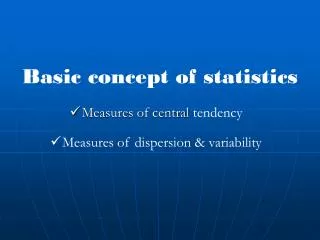
Top-down Design Methodology • We define the top-level block and identify the sub-blocks necessary to build the top-level block. • We further subdivide the sub-blocks until we come to leaf cells, which are the cells that cannot further be divided. Top level block sub block 1 sub block 2 sub block 3 sub block 4 leaf cell leaf cell leaf cell leaf cell leaf cell leaf cell leaf cell leaf cell Huai-Yi Hsu
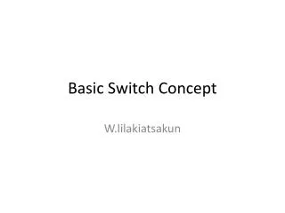
Bottom-up Design Methodology • We first identify the building block that are available to us. • We build bigger cells, using these building blocks. • These cells are then used for higher-level blocks until we build the top-level block in the design. Top level block macro cell 1 macro cell 2 macro cell 3 macro cell 4 leaf cell leaf cell leaf cell leaf cell leaf cell leaf cell leaf cell leaf cell Huai-Yi Hsu
Example: 16-bit Adder [HW] Huai-Yi Hsu
Design Encapsulation • Encapsulate structural and functional details in a module • Encapsulation makes the model available for instantiation in other modules module <Module Name> (<PortName List>); // Structural part <List of Ports> <Lists of Nets and Registers> <SubModule List> <SubModule Connections> // Behavior part <Timing Control Statements> <Parameter/Value Assignments> <Stimuli> <System Task> endmodule Huai-Yi Hsu
Instances • A module provides a template from which you can create actual objects. • When a module is invoked, Verilog creates a unique object from the template. • Each object has its own name, variables, parameters and I/O interface. Huai-Yi Hsu
Hierarchical Design Example • Model complex structural detail by instantiating modules within modules Huai-Yi Hsu
Verilog Language Rules • Verilog is a case sensitive language (with a few exceptions) • Identifiers (space-free sequence of symbols) • upper and lower case letters from the alphabet • digits (0, 1, ..., 9) • underscore ( _ ) • $ symbol (only for system tasks and functions) • Max length of 1024 symbols • Terminate lines with semicolon; • Single line comments: • // A single-line comment goes here • Multi-line comments: • /* Do not /* nest multi-line comments*/ like this */ Huai-Yi Hsu
Language Conventions • Case-sensitivity • Verilog is case-sensitive. • Some simulators are case-insensitive • Advice: - Don’t use case-sensitive feature! • Keywords are lower case • Different names must be used for different items within the same scope • Identifier alphabet: • Upper and lower case alphabeticals • decimal digits • underscore Huai-Yi Hsu
Language Conventions (cont’d) • Maximum of 1024 characters in identifier • First character not a digit • Statement terminated by ; • Free format within statement except for within quotes • Comments: • All characters after // in a line are treated as a comment • Multi-line comments begin with /* and end with */ • Compiler directives begin with // synopsys • Built-in system tasks or functions begin with $ • Strings enclosed in double quotes and must be on a single line Huai-Yi Hsu
Verilog Basis Cell • Verilog Basis Components • parameter declarations • nets or reg declarations • port declarations • Continuous assignments • Module instantiations • Gate instantiations • Function definitions • always blocks • task statements Huai-Yi Hsu
module input output reg or net net reg or net net inout net net Port Declaration • Three port types • Input port • input a; • Output port • output b; • Bi-direction port • inout c; Huai-Yi Hsu
Data Types • nets are further divided into several net types • wire, wand, wor, tri, triand, trior, supply0, supply1 • registers - stores a logic value - reg • integer - supports computation 32-bits signed • time - stores time 64-bit unsigned • real - stores values as real numbers • realtime - stores time values as real numbers • event– an event data type • Wires and registers can be bits, vectors, and arrays Huai-Yi Hsu
Integer, Real, & Time • integer counter; • initial counter = -1; • real delta; • initial delta = 4e10; • time sim_time; • initial sim_time = $time; Huai-Yi Hsu
Data Types • Nets ( wire or reg (in combinational always block) • Connects between structural elements • Must be continuously driven by • Continuous assignment (assign) • Module or gate instantiation (output ports) • Default initial value for a wire is “Z” • Registers ( reg (in sequential always block) ) • Represent abstract data storage elements • Updated at an edge trigger event and holds its value until another edge trigger event happens • Default initial value for a wire is “X” Huai-Yi Hsu
Net Types • The most common and important net types • wire and tri • for standard interconnection wires • supply 1 and supply 0 • Other wire types • wand, wor, triand, and trior • for multiple drivers that are wired-anded and wired-ored • tri0 and tri1 • pull down and pull up • trireg • for net with capacitive storage • If all drivers at z, previous value is retained Huai-Yi Hsu
Register Types • reg • any size, unsigned • integer (not synthesizable) • integet a,b; // declaration • 32-bit signed (2’s complement) • time (not synthesizable) • 64-bit unsigned, behaves like a 64-bit reg • $display(“At %t, value=%d”,$time,val_now) • real, realtime (not synthesizable) • real c,d; //declaration • 64-bit real number • Defaults to an initial value of 0 Huai-Yi Hsu
Wire & Reg • wire(wand, wor, tri) • Physical wires in a circuit • Cannot assign a value to a wire within a function or a begin…..end block • A wire does not store its value, it must be driven by • by connecting the wire to the output of a gate or module • by assigning a value to the wire in a continuous assignment • An un-driven wire defaults to a value of Z (high impedance). • Input, output, inout port declaration -- wire data type (default) Huai-Yi Hsu
Wire & Reg • reg • A variable in Verilog • Use of “reg” data type is not exactly synthesized to a really register. • Use of wire & reg • When use “wire” usually use “assign” and “assign” does not appear in “always” block • When use “reg” only use “a=b” , always appear in “always” block module test(a,b,c,d); input a,b; output c,d; reg d; assign c=a; always @(b) d=b; endmodule Huai-Yi Hsu
Wired Logic • The family of nets includes the types wand and wor • A wand net type resolves multiple driver as wired-and logic • A wor net type resolves multiple drivers as wired-or logic • The family of nets includes supply0 and supply1 • supply0 has a fixed logic value of 0 to model a ground connection • supply1 has a fixed logic value of 1 to model a power connection Huai-Yi Hsu
Data Type - Examples reg a; // scalar register wand b; // scalar net of type “wand” reg [3:0] c; // 4-bit register tri [7:0] bus; // tri-state 8-bit bus reg [1:4] d; // 4-bit trireg (small) store; // specify logical strength (rare used) wire/tri truth table wand/triand wor/trior Huai-Yi Hsu
Vector • wire and reg can be defined vector, default is 1bit • vector is multi-bits element • Format: [High#:Low#] or [Low#:High#] • Using range specify part signals wire a; // scalar net variable, default wire [7:0] bus; // 8-bit bus reg clock; // scalar register, default reg [0:23] addr; // Vector register, virtual address 24 bits wide bus[7] // bit #7 of vector bus bus[2:0] // Three least significant bits of vector bus // using bus[0:2] is illegal because the significant bit should // always be on the left of a range specification addr[0:1] // Two most significant bits of vector addr Huai-Yi Hsu
Array • Arrays are allowed in Verilog for reg, integer, time, and vector register data types. • Multidimensional array are not permitted in Verilog. integer count[0:7]; // An array of 8 count variables reg bool[31:0]; // Array of 32 one-bit Boolean register variables time chk_ptr[1:100]; // Array of 100 time checkpoint variables reg [4:0] port_id[0:7]; // Array of 8 port_id, each port_id is 5 bits wide integer matrix[4:0][4:0] // Illegal declaration count[5] // 5th element of array of count variables chk_ptr[100] // 100th time check point value port_id[3] // 3rd element of port_id array. This is a 5-bit value Huai-Yi Hsu
Memories • In digital simulation, one often needs to model register files, RAMs, and ROMs. • Memories are modeled in Verilog simply as an array of registers. • Each element of the array is known as a word, each word can be one or more bits. • It is important to differentiate between • n 1-bit registers • One n-bit register reg mem1bit[0:1023]; // Memory mem1bit with 1K 1-bit words reg [7:0] mem1byte[0:1023]; // Memory mem1byte with 1K 8-bit words mem1bit[255] // Fetches 1 bit word whose address is 255 Mem1byte[511] // Fetches 1 byte word whose address is 511 Huai-Yi Hsu
Strings • String: a sequence of 8-bits ASCII values • Special characters \n newline \t tab character \\ \ character \” “ character %% % character \abc ASCII code module string; reg [8*14:1] strvar; initial begin strvar = “Hello World”; // stored as 000000486561…726c64 strvar = “Hello World!!”; // stored as 00486561…726c642121 end endmodule Huai-Yi Hsu
Four-valued Logic • Verilog’s nets and registers hold four-valued data • 0 represent a logic zero or false condition • 1 represent a logic zero or false condition • z • Output of an undriven tri-state driver –high-impedance value • Models case where nothing is setting a wire’s value • x • Models when the simulator can’t decide the value – uninitialized or unknown logic value • Initial state of registers • When a wire is being driven to 0 and 1 simultaneously • Output of a gate with z inputs Huai-Yi Hsu
0 1 X Z 0 0 0 0 0 1 0 1 X X X 0 X X X Z 0 X X X Logic System • Four values: 0, 1, x or X, z or Z // Not case sensitive here • The logic value x denotes an unknown (ambiguous) value • The logic value z denotes a high impedance • Primitives have built-in logic • Simulators describe 4-value logic (see Appendix A in text) Huai-Yi Hsu
Resolution of Contention Between Drivers • The value on a wire with multiple drivers in contention may be x Huai-Yi Hsu
Logic Strength Levels • Types of strengths • Charge strength: trireg (large>medium>small) • Drive strength: <Net> (supply>strong>pull>weak) • Syntax • Strength level <NetType> <Strength> <Range> <Delay> <Variables>; trireg (large) [1:4] #5 c1; weakest strongest highz small medium weak large pull strong supply Huai-Yi Hsu
Number Representation • Format: <size>’<base_format><number> • <size> - decimal specification of number of bits • default is unsized and machine-dependent but at least 32 bits • <base format> - ' followed by arithmetic base of number • <d> <D> - decimal - default base if no <base_format> given • <h> <H> - hexadecimal • <o> <O> - octal • <b> <B> - binary • <number> - value given in base of <base_format> • _ can be used for reading clarity • If first character of sized, binary number 0, 1, x or z, will extend 0, 1, x or z (defined later!) Huai-Yi Hsu
Number Representation • Examples: • 6’b010_111 gives 010111 • 8’b0110 gives 00000110 • 4’bx01 gives xx01 • 16’H3AB gives 0000001110101011 • 24 gives 0…0011000 • 5’O36 gives 11100 • 16’Hx gives xxxxxxxxxxxxxxxx • 8’hz gives zzzzzzzz Huai-Yi Hsu
Net Concatenations • A easy way to group nets Huai-Yi Hsu
Parameter Declaration • Parameters are not variables, they are constants. • Typically parameters are used to specify delays and width of variables • Examples module var_mux(out, i0, i1, sel); parameter width = 2, delay = 1; output [width-1:0] out; input [width-1:0] i0, i1; input sel; assign #delay out = sel ? I1 : i0; endmodule • If sel = 1, then i1 will be assigned to out; • If sel = 0, then i0 will be assigned to out; Huai-Yi Hsu
Overriding the Values of Parameters • Module instance parameter value assignment. • Cannot skip any parameter assignment even you do not want to reassign it. module top; …… wire [1:0] a_out, a0, a1; wire [3:0] b_out, b0, b1; wire [2:0] c_out, c0, c1; var_mux U0(a_out, a0, a1, sel); var_mux #(4,2) U1(b_out, b0, b1, sel); var_mux #(3, ) U2(c_out, c0, c1, sel); …… endmodule The order of assign of parametersfollows the order of declaration of Parameters in the module. You cannot skip the delay parameter assignment. Huai-Yi Hsu
Overriding the Values of Parameters • You can use defparam to group all parameter value override assignment in one module. module top; …… wire [1:0] a_out, a0, a1; wire [3:0] b_out, b0, b1; wire [2:0] c_out, c0, c1; var_mux U0(a_out, a0, a1, sel); var_mux U1(b_out, b0, b1, sel); var_mux U2(c_out, c0, c1, sel); …… endmodule module annotate; defparam top.U0.width = 2; top.U0.delay = 1; top.U1.width = 4; top.U1.delay = 2; top.U2.width = 3; top.U2.delay = 1; endmodule Huai-Yi Hsu
Gate and Switch Level Modeling • Primitives: bottom level of the hierarchy • Verilog Gate Level Primitives • User-defined Primitives (UDP): described by truth table • Conventional modules • Behavior statements • Structural statements • Switch Level Modeling (using transistors) • Delay Specification • Specify gate delay • Specify module path delay Huai-Yi Hsu
Verilog Built-in Primitives Ideal MOS switch Resistive gates and nand or nor xor xnor buf not bufif0 bufif1 notif0 notif1 nmos pmos cmos tran tranif0 tranif1 rnmos rpmos rcmos rtran rtranif0 rtranif1 pullup pulldown Huai-Yi Hsu
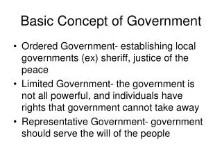
out out data data control control NMOS transistor PMOS transistor MOS Switches • Two types of MOS switches can be defined with the keywords, nmos and pmos • nmos is used to model NMOS transistors • nmos n1(out, data, control); • pmos is used to model PMOS transistors • pmos p1(out, data, control); H: stands for 1 or z L: stands for 0 or z Huai-Yi Hsu
pcontrol out data ncontrol CMOS CMOS Switches • CMOS switches are declared with the keyword cmos. • A cmos device can be modeled with a nmos and a pmos device. • cmos c1(out, data, ncontrol, pcontrol); • The cmos gate is essentially a combination of two gates: one nmos and one pmos. • nmos n1(out, data, ncontrol); • pmos p1(out, data, pcontrol); Huai-Yi Hsu
Bidirectional Switches • NMOS, PMOS, CMOS gates conduct from drain to source. • It is important to have devices that conduct in both directions. • In such cases, signals on either side of the device can be the driver signal. • Bidirectional switches are typically used to provide isolation between buses or signals. • tran t1(inout1, inout2); • tranif0 t2(inout1, inout2, control); • tranif1 t3(inout1, inout2, control); control control inout1 inout2 inout1 inout2 inout1 inout2 tran tranif1 tranif0 Huai-Yi Hsu
Power and Ground • The power (Vdd, logic 1) and Ground (Vss, logic 0) sources are needed when transistor-level circuits are designed. • Supply1 are equivalent to Vdd in circuits and place a logical 1 on a net. • Supply0 are equivalent to ground or Vss in circuits and place a logical 0 on a net. supply1 vdd; supply0 gnd; assign a = vdd; // connect a to vdd assign b = gnd; // connect b to gnd Huai-Yi Hsu
Resistive Switches • Resistive switches have the same syntax as regular switches. • Resistive devices have a high source-to-drain impedance. Regular switches have a low source-to-drain impedance. • Resistive switches reduce signal strengths when signals pass through. Regular switches retain strength levels of signals from input to output. Huai-Yi Hsu
Switches Example a out b // Define our own nor gate: nor_sw module nor_sw (out, a, b); output out; input a, b; // internal wires wire c; // set up power and ground lines supply1 pwr; supply0 gnd; //instantiate pmos switches pmos (c, pwr, b); pmos (out, c, a); //instantiate nmos switches nmos (out, gnd, a); nmos (out, gnd, b); endmodule pwr out a b gnd Huai-Yi Hsu
Primitives & UDP • Primitives are simple modules • Verilog build-in primitive gate • not, buf: • Variable outputs, single input (last port) • and, or, xor, nand, nor, xnor: • Single outputs (first port), variable inputs • User defined primitive (UDP) • Single output (first port), variable inputs • The function is specified by a truth table • Z state is not allowed Huai-Yi Hsu
Truth-Tables Models and User-Defined Primitives • Built-in primitives are for simple combinational logic gates and CMOS transistors • Primitives are memory efficient and simulate fast (good for ASIC libraries) • User-defined primitives accommodate combinational and sequential logic • Scalar output and multiple scalar inputs • Arrange inputs columns of truth table in same order as ports • Put output in last column, separated by : • Use a UDP like a built-in primitive • Table is searched top to bottom until match is found • z may not be used in table (z in simulation is treated as x) • No match results in propagation of x • See web site for more details Huai-Yi Hsu
Example UDP primitive mux_prim (mux_out, select, a, b); output mux_out; input select, a, b; table // select a b : mux_out 0 0 0 : 0 ; // Order of table columns = port order of inputs 0 0 1 : 0 ; // One output, multiple inputs, no inout 0 0 x : 0 ; // Only 0, 1, x on input and output 0 1 0 : 1 ; // A z input in simulation is treated as x 0 1 1 : 1 ; // by the simulator 0 1 x : 1 ; // Last column is the output // select a b : mux_out 1 0 0 : 0 ; 1 1 0 : 0 ; 1 x 0 : 0 ; 1 0 1 : 1 ; 1 1 1 : 1 ; 1 x 1 : 1 ; x 0 0 : 0 ; // Reduces pessimism x 1 1 : 1 ; endtable // Note: Combinations not explicitly specified will drive ‘x’ endprimitive // under simulation. Huai-Yi Hsu
Alternative model table // Shorthand notation: // ? represents iteration of the table entry over the values 0,1,x. // i.e., don't care on the input select a b : mux_out 0 0 ? : 0 ; // ? = 0, 1, x shorthand notation. 0 1 ? : 1 ; 1 ? 0 : 0 ; 1 ? 1 : 1 ; ? 0 0 : 0 ; ? 1 1 : 1 ; endtable Huai-Yi Hsu