Download
1 / 103
1.05k likes | 1.28k Views
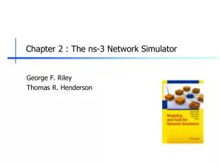
4. 1 Introduction 4.2 Virtual circuit and datagram networks 4.3 What’s inside a router 4.4 IP: Internet Protocol Datagram format IPv4 addressing ICMP IPv6. 4.5 Routing algorithms Link state Distance Vector Hierarchical routing 4.6 Routing in the Internet RIP OSPF BGP.

E N D
4. 1 Introduction 4.2 Virtual circuit and datagram networks 4.3 What’s inside a router 4.4 IP: Internet Protocol Datagram format IPv4 addressing ICMP IPv6 4.5 Routing algorithms Link state Distance Vector Hierarchical routing 4.6 Routing in the Internet RIP OSPF BGP Chapter 4: Network Layer Network Layer
transport segment from sending to receiving host on sending side encapsulates segments into datagrams on rcving side, delivers segments to transport layer network layer protocols in every host, router router examines header fields in all IP datagrams passing through it network data link physical network data link physical network data link physical network data link physical network data link physical network data link physical network data link physical network data link physical network data link physical network data link physical network data link physical application transport network data link physical application transport network data link physical Network layer Network Layer
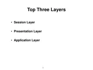
Two Key Network-Layer Functions • forwarding: move packets from router’s input to appropriate router output • routing: determine route taken by packets from source to dest. • routing algorithms Network Layer
routing algorithm local forwarding table header value output link 0100 0101 0111 1001 3 2 2 1 value in arriving packet’s header 1 0111 2 3 Interplay between routing and forwarding Network Layer
4. 1 Introduction 4.2 Virtual circuit and datagram networks 4.3 What’s inside a router 4.4 IP: Internet Protocol Datagram format IPv4 addressing ICMP IPv6 4.5 Routing algorithms Link state Distance Vector Hierarchical routing 4.6 Routing in the Internet RIP OSPF BGP Chapter 4: Network Layer Network Layer
VC: source-to-dest path, behaving much like telephone circuit used in ATM, frame-relay, X.25 not used in today’s Internet application transport network data link physical application transport network data link physical Virtual circuits 6. Receive data 5. Data flow begins 4. Call connected 3. Accept call 1. Initiate call 2. incoming call Network Layer
no call setup at network layer routers: no state about end-to-end connections no network-level concept of “connection” packets forwarded using destination host address packets between same source-dest pair may take different paths application transport network data link physical application transport network data link physical Datagram networks 1. Send data 2. Receive data Network Layer
Forwarding table 4 billion possible entries Destination Address RangeLink Interface 11001000 00010111 0001000000000000 through 0 11001000 00010111 0001011111111111 11001000 00010111 00011000 00000000 through 1 11001000 00010111 00011000 11111111 11001000 00010111 0001100100000000 through 2 11001000 00010111 0001111111111111 otherwise 3 Network Layer
Longest prefix matching Prefix MatchLink Interface 11001000 00010111 00010 0 11001000 00010111 00011000 1 11001000 00010111 00011 2 otherwise 3 Examples DA: 11001000 00010111 00010110 10100001 Which interface? DA: 11001000 00010111 00011000 10101010 Which interface? Network Layer
4. 1 Introduction 4.2 Virtual circuit and datagram networks 4.3 What’s inside a router 4.4 IP: Internet Protocol Datagram format IPv4 addressing ICMP IPv6 4.5 Routing algorithms Link state Distance Vector Hierarchical routing 4.6 Routing in the Internet RIP OSPF BGP Chapter 4: Network Layer Network Layer
Router Architecture Overview Two key router functions: • run routing algorithms/protocol (RIP, OSPF, BGP) • forwarding datagrams from incoming to outgoing link Network Layer
Input Port Functions Decentralized switching: • given datagram dest., look up output port using forwarding table in input port memory • goal: complete input port processing at ‘line speed’ • queuing: if datagrams arrive faster than forwarding rate into switch fabric Physical layer: bit-level reception Data link layer: e.g., Ethernet see chapter 5 Network Layer
Three types of switching fabrics Network Layer
Output Ports • Buffering required when datagrams arrive from fabric faster than the transmission rate • Scheduling discipline chooses among queued datagrams for transmission Network Layer
4. 1 Introduction 4.2 Virtual circuit and datagram networks 4.3 What’s inside a router 4.4 IP: Internet Protocol Datagram format IPv4 addressing ICMP IPv6 4.5 Routing algorithms Link state Distance Vector Hierarchical routing 4.6 Routing in the Internet RIP OSPF BGP 4.7 Broadcast and multicast routing Chapter 4: Network Layer Network Layer
Host, router network layer functions: • ICMP protocol • error reporting • router “signaling” • IP protocol • addressing conventions • datagram format • packet handling conventions • Routing protocols • path selection • RIP, OSPF, BGP forwarding table The Internet Network layer Transport layer: TCP, UDP Network layer Link layer physical layer Network Layer
IP protocol version number 32 bits total datagram length (bytes) header length (bytes) type of service head. len ver length for fragmentation/ reassembly fragment offset “type” of data flgs 16-bit identifier max number remaining hops (decremented at each router) upper layer time to live header checksum 32 bit source IP address 32 bit destination IP address upper layer protocol to deliver payload to E.g. timestamp, record route taken, specify list of routers to visit. Options (if any) data (variable length, typically a TCP or UDP segment) IP datagram format Network Layer
network links have MTU (max.transfer size) - largest possible link-level frame. different link types, different MTUs large IP datagram divided (“fragmented”) within net one datagram becomes several datagrams “reassembled” only at final destination IP header bits used to identify, order related fragments IP Fragmentation & Reassembly fragmentation: in: one large datagram out: 3 smaller datagrams reassembly Network Layer
length =1040 length =4000 length =1500 length =1500 ID =x ID =x ID =x ID =x fragflag =1 fragflag =0 fragflag =0 fragflag =1 offset =0 offset =0 offset =370 offset =185 One large datagram becomes several smaller datagrams IP Fragmentation and Reassembly 3980 Example • 4000 byte datagram • Head = 20 bytes • Data = 3980 bytes • MTU = 1500 bytes 1480 1480 bytes in data field 1480 offset = 1480/8 1020 Network Layer
4. 1 Introduction 4.2 Virtual circuit and datagram networks 4.3 What’s inside a router 4.4 IP: Internet Protocol Datagram format IPv4 addressing ICMP IPv6 4.5 Routing algorithms Link state Distance Vector Hierarchical routing 4.6 Routing in the Internet RIP OSPF BGP Chapter 4: Network Layer Network Layer
IP address: 32-bit identifier for host, router interface interface: connection between host/router and physical link routers typically have multiple interfaces host typically has one interface IP addresses associated with each interface 223.1.1.2 223.1.2.2 223.1.2.1 223.1.3.2 223.1.3.1 223.1.3.27 IP Addressing: introduction 223.1.1.1 223.1.2.9 223.1.1.4 223.1.1.3 223.1.1.1 = 11011111 00000001 00000001 00000001 223 1 1 1 Network Layer
Original IP Addressing: Classful ntwk host A 0 8 24 B network host 10 16 16 C network host 110 24 8 Network Layer
IP address: subnet part (high order bits) host part (low order bits) What’s a subnet ? device interfaces that can physically reach each other without intervening router with same subnet part of IP address Subnets 223.1.1.1 223.1.2.1 223.1.1.2 223.1.2.9 223.1.1.4 223.1.2.2 223.1.1.3 223.1.3.27 subnet 223.1.3.2 223.1.3.1 network consisting of 3 subnets Network Layer
Recipe To determine the subnets, detach each interface from its host or router, creating islands of isolated networks. Each isolated network is called a subnet. 223.1.1.0/24 223.1.2.0/24 223.1.3.0/24 Subnets Subnet mask: /24 Network Layer
How many? Subnets 223.1.1.2 223.1.1.1 223.1.1.4 223.1.1.3 223.1.7.0 223.1.9.2 223.1.9.1 223.1.7.1 223.1.8.1 223.1.8.0 223.1.2.6 223.1.3.27 223.1.2.1 223.1.2.2 223.1.3.1 223.1.3.2 Network Layer
host part subnet part 11001000 0001011100010000 00000000 200.23.16.0/23 IP addressing: CIDR CIDR:Classless InterDomain Routing • subnet portion of address of arbitrary length • address format: a.b.c.d/x, where x is # bits in subnet portion of address Network Layer
IP addresses: how to get one? Q: How does a host get IP address? • hard-coded by system admin • DHCP:Dynamic Host Configuration Protocol: dynamically get address from DHCP server • “plug-and-play” Network Layer
DHCP: Dynamic Host Configuration Protocol Goal: allow host to dynamically obtain its IP address from network server when it joins network • Can renew its lease on address in use • Allows reuse of addresses • Support for mobile users who want to join network (more shortly) DHCP overview: • host broadcasts “DHCP discover” msg • DHCP server responds with “DHCP offer” msg • host requests IP address: “DHCP request” msg • DHCP server sends address: “DHCP ack” msg Network Layer
E B A DHCP client-server scenario 223.1.2.1 DHCP 223.1.1.1 server 223.1.1.2 223.1.2.9 223.1.1.4 223.1.2.2 arriving DHCP client needs address in this network 223.1.1.3 223.1.3.27 223.1.3.2 223.1.3.1 Network Layer
DHCP discover src : 0.0.0.0, 68 dest.: 255.255.255.255,67 yiaddr: 0.0.0.0 transaction ID: 654 DHCP client-server scenario arriving client DHCP server: 223.1.2.5 DHCP offer src: 223.1.2.5, 67 dest: 255.255.255.255, 68 yiaddrr: 223.1.2.4 transaction ID: 654 Lifetime: 3600 secs DHCP request src: 0.0.0.0, 68 dest:: 255.255.255.255, 67 yiaddrr: 223.1.2.4 transaction ID: 655 Lifetime: 3600 secs time DHCP ACK src: 223.1.2.5, 67 dest: 255.255.255.255, 68 yiaddrr: 223.1.2.4 transaction ID: 655 Lifetime: 3600 secs Network Layer
DHCP: more than IP address DHCP can return more than just allocated IP address on subnet: • address of first-hop router for client • name and IP address of DNS sever • network mask (indicating network versus host portion of address) Network Layer
IP address block: how to get one? Q: How does an institution get a block of IP addresses? A: gets allocated portion of its provider ISP’s address space ISP's block 11001000 00010111 00010000 00000000 200.23.16.0/20 Organization 0 11001000 00010111 00010000 00000000 200.23.16.0/23 Organization 1 11001000 00010111 00010010 00000000 200.23.18.0/23 Organization 2 11001000 00010111 00010100 00000000 200.23.20.0/23 ... ….. …. …. Organization 7 11001000 00010111 00011110 00000000 200.23.30.0/23 Network Layer
200.23.16.0/23 200.23.18.0/23 200.23.30.0/23 200.23.20.0/23 . . . . . . Hierarchical addressing: route aggregation Hierarchical addressing allows efficient advertisement of routing information: Organization 0 Organization 1 “Send me anything with addresses beginning 200.23.16.0/20” Organization 2 ISP A Internet Organization 7 “Send me anything with addresses beginning 199.31.0.0/16” ISP B Network Layer
200.23.16.0/23 200.23.18.0/23 200.23.30.0/23 200.23.20.0/23 . . . . . . Hierarchical addressing: more specific routes ISP A purchases ISP B and has Organization 1 connected to ISP B Organization 0 “Send me anything with addresses beginning 200.23.16.0/20” Organization 2 ISP A Internet Organization 7 “Send me anything with addresses beginning 199.31.0.0/16 or 200.23.18.0/23” ISP B Organization 1 Network Layer
IP addressing: the last word... Q: How does an ISP get block of addresses? A: ICANN: Internet Corporation for Assigned Names and Numbers • allocates addresses • manages DNS • assigns domain names, resolves disputes Network Layer
Typical home network components: DSL or cable modem router Ethernet wireless access point Home networks wireless laptops to/from cable headend cable modem router wireless access point Ethernet Introduction
Private IP Addresses • Three blocks of IP addresses are reserved for private networks: • 10.0.0.0 - 10.255.255.255 10.0.0.0/8 • 172.16.0.0 - 172.31.255.255 172.16.0.0/11 • 192.168.0.0 - 192.168.255.255 192.168.0.0/16 Network Layer
NAT: Network Address Translation rest of Internet local network (e.g., home network) 10.0.0/24 10.0.0.1 10.0.0.4 10.0.0.2 138.76.29.7 10.0.0.3 Datagrams with source or destination in this network have 10.0.0.0/24 address for source, destination (as usual) All datagrams leaving local network have same single source NAT IP address: 138.76.29.7, different source port numbers Network Layer
NAT: Network Address Translation • Motivation: local network uses just one IP address as far as outside world is concerned: • range of addresses not needed from ISP: just one IP address for all devices • can change addresses of devices in local network without notifying outside world • can change ISP without changing addresses of devices in local network • devices inside local net not explicitly addressable, visible by outside world (a security plus). Network Layer
NAT: Network Address Translation Implementation: NAT router must: • outgoing datagrams:replace (source IP address, port #) of every outgoing datagram to (NAT IP address, new port #) . . . remote clients/servers will respond using (NAT IP address, new port #) as destination addr. • remember (in NAT translation table) every (source IP address, port #) to (NAT IP address, new port #) translation pair • incoming datagrams:replace (NAT IP address, new port #) in dest fields of every incoming datagram with corresponding (source IP address, port #) stored in NAT table Network Layer
2 4 1 3 S: 138.76.29.7, 5001 D: 128.119.40.186, 80 S: 10.0.0.1, 3345 D: 128.119.40.186, 80 1: host 10.0.0.1 sends datagram to 128.119.40.186, 80 2: NAT router changes datagram source addr from 10.0.0.1, 3345 to 138.76.29.7, 5001, updates table S: 128.119.40.186, 80 D: 10.0.0.1, 3345 S: 128.119.40.186, 80 D: 138.76.29.7, 5001 NAT: Network Address Translation NAT translation table WAN side addr LAN side addr 138.76.29.7, 5001 10.0.0.1, 3345 …… …… 10.0.0.1 10.0.0.4 10.0.0.2 138.76.29.7 10.0.0.3 4: NAT router changes datagram dest addr from 138.76.29.7, 5001 to 10.0.0.1, 3345 3: Reply arrives dest. address: 138.76.29.7, 5001 Network Layer
NAT traversal problem • client wants to connect to server with address 10.0.0.1 • server address 10.0.0.1 local to LAN (client can’t use it as destination addr) • only one externally visible NATted address: 138.76.29.7 • solution 1: statically configure NAT to forward incoming connection requests at given port to server • e.g., (123.76.29.7, port 2500) always forwarded to 10.0.0.1 port 25000 10.0.0.1 Client ? 10.0.0.4 138.76.29.7 NAT router Network Layer
NAT traversal problem • solution 2: Universal Plug and Play (UPnP) Internet Gateway Device (IGD) Protocol. Allows NATted host to: • learn public IP address (138.76.29.7) • add/remove port mappings (with lease times) i.e., automate static NAT port map configuration 10.0.0.1 IGD 10.0.0.4 138.76.29.7 NAT router Network Layer
10.0.0.1 NAT router NAT traversal problem • solution 3: relaying (used in Skype) • NATed client establishes connection to relay • External client connects to relay • relay bridges packets between to connections 2. connection to relay initiated by client 1. connection to relay initiated by NATted host 3. relaying established Client 138.76.29.7 Network Layer
10.0.0.1 Skype relay • When a client signs in, it is assigned a super-peer • When A calls B, the call is forwarded to B through A’s and B’s super-peers. • If the call is accepted, a relay node is selected. • A and B are instructed to make a connection to the relay node. Super-peer Client (behind NAT) Super-peer (not behind NAT) Network Layer
Types of NAT • NAT not standardized • Different NAT-routers behave differently • A traversal technique does not necessarily work for all NAT routers • Different types of NAT • Full cone • Restricted cone • Port-restricted cone • Symmetric Network Layer
Full-cone NAT server 1 NAT-router client server 2 Network Layer
(Address) Restricted cone NAT server 1 NAT-router client server 2 Restricted to IP addresses to which client has ever sent a packet via this (addr, port) mapping Network Layer
Port restricted cone NAT server 1 NAT-router client server 2 Restricted to external ports to which client has ever sent a packet via this (addr, port) mapping Network Layer
Symmetric NAT server 1 NAT-router client server 2 Network Layer