Download
1 / 66
660 likes | 695 Views
This summary covers the dynamic modeling aspects of UML, including State, Sequence, Collaboration, and Activity diagrams. Learn how dynamic diagrams capture essential system dynamics, focusing on communication, interaction, and state transitions. Get insights on symbol notations, object relations, and intra-object relationships. Discover the purpose and key components of State diagrams, helping document class states, transitions, events, and operations.

E N D
UNIT 3 Object OrientedAnalysis and Designwith UML
Summary Unit 2... • UML Overview • Model systems using OO concepts • Information systems, technical systems, system software, real time, distributed system,… • UML is a modeling language • Based on the notion of views • Use case, logical, component, concurrency, deployment view
Summary Unit 2... • UML Diagrams • Extensibility of the UML • Stereotypes, tagged values, constraints • Use-Case diagram • Class diagram • Object diagram • State diagram • Sequence diagram • Collaboration diagram • Activity diagram • Component diagram • Deployment diagram
Summary Unit 2... • Static Modeling with UML • Use Case Diagrams • to capture the functional requirements of a system • informally stated in natural language • focus on what the system is supposed to do • Class Diagrams • A view of the system in terms of classes and relationships • Behaviour as well as information in the system is modeled • This static model of the system is built in a dynamic way !!
Operator Customer Use-Case Diagram Print Daily Report Return Item Change Item Data
Steps for Building a Use Case Model • Define the boundaries of the system • Find the actors and use cases • Define the relationships between the use cases • Validate and verify the model • Highly interactive with the end users ! • Should include discussions Be Creative !
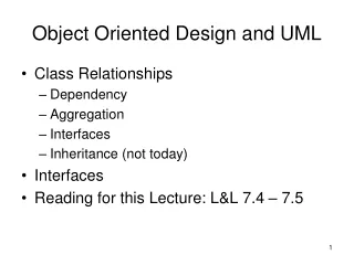
Relationships Between Classes • An association is a connection between classes • A generalization is a relationship between a more general and a more specific element • A dependency is a relationship between elements, one independent another dependent • A refinement is a relationship between two descriptions of the same thing but at different levels of abstraction
UNIT 3 TheUnifiedModellingLanguage (continued)
Unit 3 : Outline • Dynamic Modelling • State Diagrams • Sequence Diagrams • Collaboration Diagrams • Activity Diagrams
Dynamic Modeling... • Describes what happens at run-time • Objects vs Classes • How do elements of static diagrams : • Cooperate to manage their tasks • Communicate with each other • Change their state • Provide the functionality of the system • Method outline and messages flow • For capturing difficult to understand aspects Complements Static Diagrams
Dynamic Modeling. • Focus on communicating one aspect of a system’s dynamics • Model only those elements that are essential • Provide detail consistent with the level of abstraction • Sometimes a piece of code says more than lines, rectangles, ...
Different Dynamic Diagrams • Sequence Diagrams • Focus on time aspect of interaction and communication • Collaboration Diagrams • Focus on space aspect of interaction and communication • State Diagrams • Focus on state, behaviour and events • Activity Diagrams • Focus on work aspect of interaction and communication Inter-object relation Intra-object relation
Unit 3 : Outline • Dynamic Modelling • State Diagrams • Sequence Diagrams • Collaboration Diagrams • Activity Diagrams
Focus on • The possible states of the instances of a class • The possible transitions from one state to another one • The events firing transitions • The operations which are executed within states or during a transition Intra-object relation
Purpose of State diagrams • To document classes that have : • Clearly identifiable states • State = {ongoing_behaviour, attributes, ...} • Complex behaviour • Many events (signals)
Notation State Diagrams. State Initial State Final State State Transition
Parts of a State Diagram State Box Initial State Final State Name State Variables Activities State Transition
Example State Diagram Onfirst floor Movingup go up(floor) Arriveat first floor Moving tofirst floor Arriveat floor go up(floor) Arriveat floor Movingdown Idle go down(floor) State Diagram for the Elevator Class time-out
Parts of a State Box State Name Login State Variables Login time = Current time Entry/type “login”Exit/login (user name, password)Do/get user nameDo/get passwordHelp/display Help Activity Actions Atomic Can be further decomposed
Login Login time = Current time Entry/type “login”Exit/login (user name, password)Do/get user nameDo/get passwordHelp/display Help Activities Part of a State Box... • Describes the actions undertaken when the object is in a particular state • These actions are guided by events Event-name argument-list ‘/’ action-expression
Activities Part of a State Box. • Standard events : Action is executed whenentering the state Entry / Action Action is executed whenleaving the state Exit / Action Activity is executed, parametersare allowed Do / Activity Event is handled withinthe state event / Action
State Transition Events… • Four kinds of events in UML : • A condition becoming true • shown as a guard condition on a state transition ChangeEvent • Receipt of a message • shown as an event signature on state transitions Call Event
State Transition Events… • A relative or absolute point in time • shown as a time expression on state transition Time Event • Signal Event : The receipt of a signal • <<error>> out_of_memory • keyPressed, … Signal Event
State Transition Events… DigitalWatch Messages vs Events modeButton()inc() inc/hours := hours +1 inc/minutes := minutes +1 Set hours Display Set minutes modeButton() modeButton() do/displayhours do/displaycurrent time do/displayminutes modeButton()
State Transition Labels (all optional) • Examples : • draw(f : Figure, c : Color) • redraw • redraw() • print(invoice) event-signature '[' guard-condition ']' '/' action-expression '^' send-clause event-signature = event-name '(' parameter ',',... ')'
State Transition Labels… event-signature '[' guard-condition ']' '/' action-expression '^' send-clause Guard-condition = A boolean expression placed on a state transition • Examples : • [t = 15sec] • [number of invoices > n] • [withdrawal (amount) && balance >= amount ] • Guards are mutual exclusive
State Transition Labels… event-signature '[' guard-condition ']' '/' action-expression '^' send-clause Action-expression = Is executed when the transition fires • Examples : • increase () / n := n + 1 • add (n) / sum := sum + n No nesting or recursion allowed
State Transition Labels. event-signature '[' guard-condition ']' '/' action-expression '^' send-clause Send-clause = Explicit syntax for sending a message during a transition between two states • Examples : • ^ pen.set(color) • [timer = Time-out] ^ self.go down (first floor)
Example : Digital Watch inc/hours := hours +1 modulo 24 inc/minutes := minutes +1 modulo 60 Set hours Display Set minutes modeButton() modeButton() do/displayhours do/displaycurrent time do/displayminutes modeButton()
Communication between Diagrams Remote Control On() Off On Off() Play() Stop() Play() On() Off() Stop() CD Player Play() On() Off On/Stop On/Play Stop() Off() Off()/Stop()
Substates… AND-STATES Running Forward Backward Low speed High speed States that may be true at the same time
Substates. OR-STATES Running Forward Backward States that may not be true at the same time
Unit 3 : Outline • Dynamic Modelling • State Diagrams • Sequence Diagrams • Collaboration Diagrams • Activity Diagrams
Sequence diagram Symbols Object 1 Object 2 Object 3
Focus on • The interaction and communication between objects • Specify the realization of an operation or use case • Message sequences • Time aspect • Cfr Collaboration diagram
Two Available Forms • Generic form • documents all possible alternatives in a scenario • conditions, loops, branches are possible • cfr class diagram • Instance form • documents one possible interaction • no conditions, loops, or branches • cfr object diagram :Computer C1:Computer or C1
Different Message Types • Only means of communication with objects are messages Synchronous Asynchronous Simple Synchronous with Immediate return
Notation Sequence Diagrams… Print(ps-file) :Computer :PrintServer :Printer Print(ps-file) [no queue]Print(ps-file)
Notation Sequence Diagrams. :Computer Object Lifeline Activation Print(ps-file) Message send Return [no queue]Print(ps-file) Guard condition
Labels for Iteration message1() C1:C D1:D D2:D send message2 until … message2() message3()
Labels for Constraints Print(ps-file) :Computer :PrintServer :Printer Print(ps-file) a Print(ps-file) {b - a < 5 sec} b {b’ – b < 1 sec} b’ • If PrinterServer receives a file, it should transmit this file to the Printer within 5 sec • Communicating the file from the PrinterServer to the Printer should take less than 1 sec
Object creation NewCustomer(Data) :CustomerWindow Customer(Data) :Customer
Object Destruction RemoveCustomer( ) :CustomerWindow :Customer DeleteCustomer( )
Unit 3 : Outline • Dynamic Modelling • State Diagrams • Sequence Diagrams • Collaboration Diagrams • Activity Diagrams
Focus on • The interaction and communication between objects • Shows the static and dynamic relationships between objects – the context aspect • Space aspect(time is no dimension on its own) • Sequence indicated with numbers
Example Collaboration Diagram :Computer Print(ps-file) 1:Print(ps-file) [printer free] 1.1:Print(ps-file) :PrinterServer :Printer