Download
1 / 18
190 likes | 375 Views
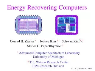
Advanced Computer Architecture Laboratory Department of Electrical Engineering and Computer Science University of Michigan Ann Arbor, MI. Energy Recovering ASIC Design. Conrad H. Ziesler Joohee Kim Marios C. Papaefthymiou. Scale voltage to reduce swing

E N D
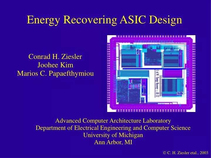
Advanced Computer Architecture Laboratory Department of Electrical Engineering and Computer Science University of Michigan Ann Arbor, MI Energy Recovering ASIC Design Conrad H. Ziesler Joohee Kim Marios C. Papaefthymiou
Scale voltage to reduce swing Pipeline to meet throughput target Total dissipation decreases… Design for Low Power
Clock Power Dissipation Pipelining Voltage scaling … but fraction of clock power increases Typical approach to reduce clock power: clock gating Cons: design complexity and cost
Main idea Recycle energy stored in circuit capacitance Inter-dependent research issues 1. Which capacitance to recover from? 2. How to store/reuse recovered energy? 3. What circuits to do the recovery? An Alternative Approach: Energy Recovery 3. 1. 2.
Non-Dissipative rail-drivers for adiabatic circuits S.G. Younis, T.F. Knight, Jr. -- ARVLSI'95 Clock-Powered CMOS: A Hybrid Adiabatic Logic Style for Energy-Efficient Computing N. Tzartzanis, W. C. Athas -- ARVLSI'99 Driving a capacitive load without dissipating fCV2 L. Svensson and J. G. Koller -- SLPE'94 A low power sinusoidal clock B. Voss, M. Glesner -- ISCAS'01 And many, many others.... Few real working chips, however. Previous Work in Energy Recovery
Energy recovery technologies for reducing clock dissipation Single-phase sinusoidal clock Efficient, LC resonant clock generator Low power sinusoidally clocked flip-flop Key attributes Compatible with ASIC design flow, low overhead High frequency (200-500MHz) Low voltage (1.0-1.5V) Real, working chips (in 0.25mm logic process) Our Contributions
PTERF: Energy recovering flip-flop Clock signal: Single phase, resonant sinusoid Dissipates only when D and Q are switching Low voltage operation at high speeds Delay similar to conventional flip-flop Fully compatible with standard-cell design flows Introducing PTERF 16 transistors 84 mm2
PTERF Characterization Delay D-Q Varies with frequency Constant 25% of clock cycle Similar to conventional ffs Energy per cycle Idle: D, Q constant Active: D, Q changing Order of magnitude difference
Resonant Clock Generator Driver Resonate entire clock capacitance with small inductor Pump resonant system with NMOS switch at appropriate times NMOS switch only conducts incremental losses whenever ON NMOS Switch Pre-driver Control
Simulation Based Evaluation • Designed ASIC with • PTERF • resonant clock generator • Dual-mode system • conventional • energy recovery • Direct comparison of dissipation at target throughput
ASIC Statistics Discrete wavelet transform 3897 gates, 413 ffs 15571 transistors 400mm x 900mm 13.6 pF , 21 nH 300 MHz , 1.5V 0.25mm logic process Clock generator Dual-mode DWT
Simulation Results Total system dissipation Conventional mode includes clock tree Energy recovery mode includes on-chip clock generator
Summary • Technologies for reducing clock dissipation through energy recovery • Novel flip-flop • Novel resonant clock generator • Drop-in replacement for clocking system in conventional ASIC design flow • Complexity of explicit clock gating eliminated • Simulation of DWT ASIC at 300 MHz • 4X savings when idle • 15% savings when active
Acknowledgments and Links Funded in part by U.S. Army Research Office DAAG-55-97-1-0250 DAAD-19-99-1-0340 For more information please visit www.eecs.umich.edu/acal/energyrecovery