Download
1 / 50
510 likes | 798 Views
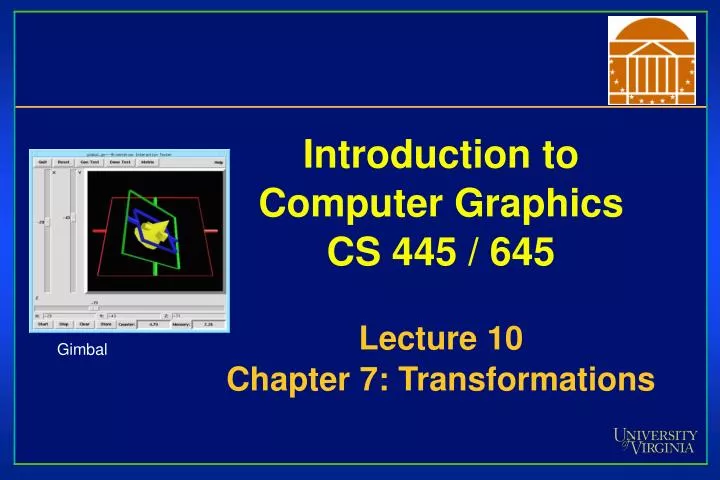
Introduction to Computer Graphics CS 445 / 645 Lecture 10 Chapter 7: Transformations. Gimbal. Overview. Rotation representations Euler Axis-angle Quaternion Camera Transformations Projections. Basic 3D Transformations. Rotate around Z axis:. Rotate around Y axis:. Rotate around X axis:.

E N D
Introduction to Computer GraphicsCS 445 / 645Lecture 10Chapter 7: Transformations Gimbal
Overview • Rotation representations • Euler • Axis-angle • Quaternion • Camera Transformations • Projections
Basic 3D Transformations Rotate around Z axis: Rotate around Y axis: Rotate around X axis:
3-D Rotation • General rotations in 3-D require rotating about an arbitraryaxis of rotation • Deriving the rotation matrix for such a rotation directly is a good exercise in linear algebra • Standard approach: express general rotation as composition ofcanonical rotations • Rotations about X, Y, Z
Composing Canonical Rotations • Goal: rotate about arbitrary vector A by • Idea: we know how to rotate about X,Y,Z • So, rotate about Y by until A lies in the YZ plane • Then rotate about X by until A coincides with +Z • Then rotate about Z by • Then reverse the rotation about X (by -) • Then reverse the rotation about Y (by -)
Composing Canonical Rotations • First: rotating about Y by until A lies in YZ • How exactly do we calculate ? • Project A onto XZ plane (Throw away y-coordinate) • Find angle that rotates A to x-axis: = -(90° - ) = - 90 ° • Second: rotating about x-axis by until A lies on z-axis • How do we calculate ?
Composing Matrices • So we have the following matrices: • p: The point to be rotated about A by • Ry : Rotate about Y by • Rx : Rotate about X by • Rz : Rotate about Z by • Rx -1: Undo rotation about X by • Ry-1: Undo rotation about Y by • In what order should we multiply them?
Compositing Matrices • Short answer: the transformations, in order, are written from right to left • In other words, the first matrix to affect the vector goes next to the vector, the second next to the first, etc. • So in our case: • p’ = Ry-1 Rx -1 Rz Rx Ry p
Rotation Matrices • Notice these two matrices: • Rx : Rotate about X by • Rx -1: Undo rotation about X by • How can we calculate Rx -1?
Rotation Matrices • Notice these two matrices: • Rx : Rotate about X by • Rx -1: Undo rotation about X by • How can we calculate Rx -1? • Obvious answer: calculate Rx (-) • Clever answer: exploit fact that rotation matrices are orthonormal
Rotation Matrices • Notice these two matrices: • Rx : Rotate about X by • Rx -1: Undo rotation about X by • How can we calculate Rx -1? • Obvious answer: calculate Rx (-) • Clever answer: exploit fact that rotation matrices are orthonormal • What is an orthonormal matrix? • What property are we talking about?
Rotation Matrices • Orthonormal matrix: • orthogonal (columns/rows linearly independent) • normalized (columns/rows length of 1) • The inverse of an orthogonal matrix is just its transpose:
Representing 3 Rotational DOFs • 3x3 Matrix (9 DOFs) • Rows of matrix define orthogonal axes • Euler Angles (3 DOFs) • Rot x + Rot y + Rot z • Axis-angle (4 DOFs) • Axis of rotation + Rotation amount • Quaternion (4 DOFs) • 4 dimensional complex numbers
Rotation Matrices • What did we start with? • 3 rotations (roll, pitch, yaw) • Three numbers • Called Euler Angles • Axis-angle • Four numbers • And we end up with a 4x4 transformation matrix • Where inner 3x3 describes rotation
Really, a whole matrix to represent three numbers? Underconstrained? • 9 DOFs must reduce to 3 • Rows must be unit length (-3 DOFs) • Rows must be orthogonal (-3 DOFs) • Drifting matrices is very bad • Numerical errors results when trying to gradually rotate matrix by adding derivatives • Resulting matrix may scale / shear • Gram-Schmidt algorithm will re-orthogonalize your matrix • Difficult to interpolate between matrices • Why would we do this?
Euler Angles • (qx, qy, qz) = RzRyRx • Rotate qx degrees about x-axis • Rotate qy degrees about y-axis • Rotate qz degrees about z-axis • Axis order is not defined • (y, z, x), (x, z, y), (z, y, x)… are all legal • Pick one
Euler Angles • Rotations not uniquely defined • ex: (z, x, y) = (90, 45, 45) = (45, 0, -45)takes positive x-axis to (1, 1, 1) • Cartesian coordinates are independent of one another, but Euler angles are not • Gimbal Lock • Term derived from mechanical problem that arises in gimbal mechanism that supports a compass or a gyro
A Gimbal • Hardware implementation of Euler angles (used for mounting gyroscopes and globes)
Gimbal Lock • Occurs when two axes are aligned • Second and third rotations have effect of transforming earlier rotations • ex: Rot x, Rot y, Rot z • If Rot y = 90 degrees, Rot z == -Rot x
Gimbal Lock http://www.anticz.com/eularqua.htm
Interpolation • Interpolation between two Euler angles is not unique • ex: (x, y, z) rotation • (0, 0, 0) to (180, 0, 0) vs. (0, 0, 0) to (0, 180, 180) • Interpolation about different axes are not independent
Axis-angle Notation • Define an axis of rotation (x, y, z) and a rotation about that axis, q: R(q, n) • 4 degrees of freedom specify 3 rotational degrees of freedom because axis of rotation is constrained to be a unit vector
Axis-angle Rotation Given r – Vector in space to rotate n – Unit-length axis in space about which to rotate q – The amount about n to rotate Solve r’ – The rotated vector r’ r n
Axis-angle Rotation • Step 1 • Compute rk an extended version of the rotation axis, n • rk = (n ¢ r) n rk r’ r
Axis-angle Rotation • Compute r? • r? = r – (n ¢ r) n r? r’ r
v q Axis-angle Rotation • Compute v, a vector perpendicular to rk and r? • v = rk£ r? • Use v and r? and q to compute r’ cos(q) r? + sin(q) v r?
rperp = r – (n.r) n q V = nx (r – (n.r) n) = nxr Rr rpar = (n.r) n r n Axis-angle Notation Rr = Rrpar + Rrperp = Rrpar + (cos q) rperp + (sin q) V =(n.r) n + cos q(r – (n.r)n) + (sin q) n x r = (cos q)r + (1 – cos q) n (n.r) + (sin q) n x r
Axis-angle Notation • No easy way to determine how to concatenate many axis-angle rotations that result in final desired axis-angle rotation • No simple way to interpolate rotations
Quaternion • Remember complex numbers: a + ib • Where i2 = -1 • Invented by Sir William Hamilton (1843) • Remember Hamiltonian path from Discrete II? • Quaternion: • Q = a + bi + cj + dk • Where i2 = j2 = k2 = -1 and ij = k and ji = -k • Represented as: q = (s, v) = s + vxi + vyj + vzk
Quaternion • A quaternion is a 4-D unit vector q = [x y z w] • It lies on the unit hypersphere x2 + y2 + z2 + w2 = 1 • For rotation about (unit) axis v by angle q • vector part = (sin q/2) v = [x y z] • scalar part = (cos q/2) = w • (sin(q/2) vx, sin(q/2) vy, sin(q/2) vz, cos (q/2)) • Only a unit quaternion encodes a rotation - normalize
Quaternion • Rotation matrix corresponding to a quaternion: • [x y z w] = • Quaternion Multiplication • q1 * q2 = [v1, w1] * [v2, w2] = [(w1v2+w2v1+ (v1 x v2)), w1w2-v1.v2] • quaternion * quaternion = quaternion • this satisfies requirements for mathematical group • Rotating object twice according to two different quaternions is equivalent to one rotation according to product of two quaternions
Quaternion Example • X-roll of p • (cos (p/2), sin (p/2) (1, 0, 0)) = (0, (1, 0, 0)) • Y-roll 0f p • (0, (0, 1, 0)) • Z-roll of p • (0, (0, 0, 1)) • Ry (p) followed by Rz (p) • (0, (0, 1, 0) times (0, (0, 0, 1)) = (0, (0, 1, 0) x (0, 0, 1) = (0, (1, 0, 0))
Quaternion Interpolation • Biggest advantage of quaternions • Interpolation • Cannot linearly interpolate between two quaternions because it would speed up in middle • Instead, Spherical Linear Interpolation, slerp() • Used by modern video games for third-person perspective • Why?
SLERP • Quaternion is a point on the 4-D unit sphere • interpolating rotations requires a unit quaternion at each step • another point on the 4-D unit sphere • move with constant angular velocity along the great circle between two points • A great circle is a section of a sphere that contains a diameter of the sphere (Kern and Bland 1948, p. 87). • Any rotation is defined by 2 quaternions, so pick the shortest SLERP • To interpolate more than two points, solve a non-linear variational constrained optimization • Ken Shoemake in SIGGRAPH ’85 (www.acm.org/dl)
Quaternion Interpolation • Quaternion (white) vs. Euler (black) interpolation • Left images are linear interpolation • Right images are cubic interpolation
Quaternion Code • http://www.gamasutra.com/features/programming/19980703/quaternions_01.htm • Registration required • Camera control code • http://www.xmission.com/~nate/smooth.html • File, gltb.c • gltbMatrix and gltbMotion
3D Rendering Pipeline (for direct illumination) 3D Geometric Primitives Modeling Transformation Transform into 3D world coordinate system Lighting Illuminate according to lighting and reflectance Viewing Transformation Transform into 3D camera coordinate system Projection Transformation Transform into 2D screen coordinate system Clipping Clip primitives outside camera’s view Scan Conversion Draw pixels (includes texturing, hidden surface, ...) Image
Reminder: Homogeneous Coords • What effect does the following matrix have? • Conceptually, the fourth coordinate wis a bit like a scale factor
Homogenous Coordinates • Increasing w makes things smaller • We think of homogenous coordinates as defining a projective space • Increasing w “getting further away” • Will come in handy for projection matrices
Projection Matrix • We talked about geometric transforms, focusing on modeling transforms • Ex: translation, rotation, scale, gluLookAt() • These are encapsulated in the OpenGL modelview matrix • Projection is also represented as a matrix • Next few slides: representing orthographic and perspective projection with the projection matrix
Taxonomy of Projections FVFHP Figure 6.10
Parallel Projection • Center of projection is at infinity • Direction of projection (DOP) same for all points View Plane DOP Angel Figure 5.4
Orthographic Projections • DOP perpendicular to view plane Front Angel Figure 5.5 Top Side
Oblique Projections • DOP not perpendicular to view plane Cavalier (DOP = 45o) Cabinet (DOP = 63.4o) H&B Figure 12.24
Orthographic Projection • Simple OrthographicTransformation • Original world units are preserved • Pixel units are preferred
Orthographic: Screen Space Transformation left =10 m right = 20 m top=20 m (max pixx, max pixy) (height in pixels) (0, 0) bottom=10 m (width in pixels)
Orthographic: Screen Space Transformation • left, right, top, bottom refer to the viewing frustum in modeling coordinates • width and height are in pixel units • This matrix scales and translates to accomplish the transition in units