Download
1 / 13
150 likes | 496 Views
Arduino DC motor driver L239 H-Bridge Arduino GUI vs Atmel Studio. Stefan Pirvu ADCES 2015. Content. Arduino board review Serial communication, writing C# app in order to communicate over serial - code Using H-Bridge to power DC motors PWM vs. continuous voltage drive Arduino GUI - code

E N D
Arduino DC motor driverL239 H-BridgeArduino GUI vs Atmel Studio Stefan Pirvu ADCES 2015
Content • Arduino board review • Serial communication, writing C# app in order to communicate over serial - code • Using H-Bridge to power DC motors • PWM vs. continuous voltage drive • Arduino GUI - code • Atmel Studio - code
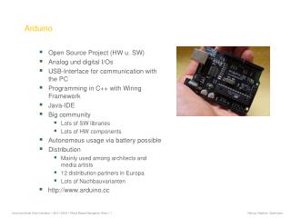
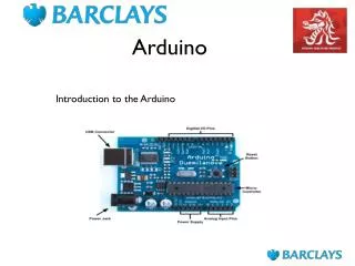
Arduino board review • USB support • 16MHz • 32k flash • 14 I/O pins • 5 PWM pins • 6 ADC pins
Serial communication, writing C# app in order to communicate over serial • CODE
L298 • http://www.tech.dmu.ac.uk/~mgongora/Resources/L298N.pdf • Cheap aprox. 10-20 RON • Dual H-Bridge
PWM vs. continuous voltage drive • Analog • bad at low voltages • needs mechanical switches • ranges depend on the number of resistors • very resistant over time • Digital • good at low voltages • fine control • buzz sounds
Arduino GUI • http://arduino.cc/ • CODE
Atmel Studio • http://www.atmel.com/microsite/atmel_studio6/ • But before coding… • http://www.atmel.com/images/Atmel-8271-8-bit-AVR-Microcontroller-ATmega48A-48PA-88A-88PA-168A-168PA-328-328P_datasheet_Complete.pdf • http://arduino.cc/en/Tutorial/SecretsOfArduinoPWM
ATMEGA328P AIN0/OC0A/PCINT22 – Port D, Bit 6 OC0A, Output Compare Match output: The PD6 pin can serve as an external output for the Timer/Counter0. Compare Match A. The PD6 pin has to be configured as an output (DDD6 set (one)) to serve this function. The OC0A pin is also the output pin for the PWM mode timer function. T1/OC0B/PCINT21 – Port D, Bit 5 OC0B, Output Compare Match output: The PD5 pin can serve as an external output for the Timer/Counter0. Compare Match B. The PD5 pin has to be configured as an output (DDD5 set (one)) to serve this function. The OC0B pin is also the output pin for the PWM mode timer function.
ATMEGA328 Timer/Counter • LET’S CODE Timer Registers Several registers are used to control each timer. The Timer/Counter Control Registers TCCRnA and TCCRnB hold the main control bits for the timer. (Note that TCCRnA and TCCRnB do not correspond to the outputs A and B.) These registers hold several groups of bits: Waveform Generation Mode bits (WGM): these control the overall mode of the timer. (These bits are split between TCCRnA and TCCRnB.) Clock Select bits (CS): these control the clock prescaler Compare Match Output A Mode bits (COMnA): these enable/disable/invert output A Compare Match Output B Mode bits (COMnB): these enable/disable/invert output B
Use AVRDude to upload HEX • >C:\Program Files\Arduino\hardware\tools\avr\bin • avrdude.exe -C”C:ProgramFiles\Arduino\hardware\tools\avr\etc\avrdude.conf” f -patmega328p -carduino -P\.COM4 -b115200 -D -Uflash:w:”$(ProjectDir)Debug$(TargetName).hex”:i
Thank you • QUESTIONS?? • Code files: