Download

1 / 42
420 likes | 549 Views
Under-balanced well bore cleanout and production evaluation technology. Presentation Overview. Why This Technology is Required How It Works Applications Benefits Case Histories & Successes. Why is This Technology Required. Under-pressured reservoirs

E N D
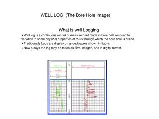
Under-balanced well bore cleanout and production evaluation technology.
Presentation Overview Why This Technology is Required How It Works Applications Benefits Case Histories & Successes
Why is This Technology Required • Under-pressured reservoirs • Horizontal and extended reach well designs • Velocities in liners allow for solids settling • Hz section is not 100% utilized • Liquid loading of shallow to medium depth well bores • Cleanout damage is becoming more of a problem each and every day
Why This Technology is Required • Alternative processes such as fluid circulation, swabbing, gas cleanouts and bailing or pump to surface technology have limitations and can no longer be generally applied. • Adds pressure to formation (over-balanced) • Does not work in Hz • Costly to deploy • Slow process ---› expensive
How it Works This systems utilizes two unique technologies to revolutionize the well bore cleanout operations. Our JetPak™ system utilizes FlatPak™ coiled tubing technology as well as specifically engineered jet pump to remove solids and liquids from well bores. The primary function of this technology is to create a low pressure environment in the well bore to pump the fluid and/or solids to surface.
Venturiprinciple, applies to JetPak & JetVak Injection Pressure Velocity Surface Returns Pressure Pump Intake Pump Discharge Suction Pressure Velocity
Applications Class I and II vertical, deviated, slant or horizontal well bore cleanouts Produced or frac sand cleanouts Acid frac/stimulation cleanup Drilling fluid recovery Production testing/evaluation
Text Book “Cleanout Damage” Conventional Cleanout Event Conventional Cleanout Damage Conventional Cleanout Event Typical Well Response From Conventional CT Cleanout:
Benefits Production Testing - This is an excellent system to evaluate wells that are sub-pressured in nature and do not flow. The subject well may be a candidate for Artificial Lift or an abandonment candidate. None the less, the JetPak™ will remove the fluid so accurate well data can be collected.
Vertical heavy oil (10 API) well production test BH recorder data Well is pumped off, pressure changes are from moving the FlatPak and BH pump
Run To TD 1,000 kPa / 145 psi Tool at Wellhead: 135 kPa / 20 psi Tool at Wellhead: 160 kPa / 23 psi On Bottom BHA Pressure & Temperature Job Data: Gas Column while RIH: 165 kPa / 24 psi Run In Hole Pull Out of Hole
∆P : 13 kPa (2 psi) 0.7 m3 in ½ Hour On Bottom BHA Pressure & Temperature Job Data: Run In Hole Pull Out of Hole
JetPak versus JetVak? Quantum JetVak video final.wmv • JetPak system alternates between Jetting and vakking (shiftable while down hole) • JetVak system facilitates simultaneous jetting and vakking operations, a “clean as you go approach. • The FlatPak coiled tubing string is bonded and contains dual 1¼” or1½” carbon steel coils. • The length of the string ranges from 900 to 3100 meters, and is deployed by Technicoil’s rig 2006 based out of Red Deer, supported by Quantum. Areas of Application • Lower Amaranth SW Manitoba • Viking • Manville and Colorado group • CHOPS Vertical & Hz Lloyd. Slave Lk. And Wabasca • Shaunovan, Bakken and Cardium • Banff • Dina
Case Histories & Successes Husky CHOPS Hz under pressure well cleanout with JetPak • 0.8m3 sand • Up to 30% sand - avg. 6% through job • 3.5m3 of fluid • 740TVD • 1550MD • 114mm guide string in 137mm • liner This well was 1yr old and did not produce, unknown problem. The well is now producing at 10m3/day yielding Husky a daily cash flow of over $3000.00
Case Histories & Successes JetVak cleanout Oct. 15 2010, 0.7M3 sand
PennWestDenzil Hz CO, BH rec data 3.2m3 of 2350kg/m3 of fine sand 21% of liner volume. BHP increases as we move into slotted liner
Shell Canada CSS perf. Liner CO, BH rec data Solids bridges indicated on either side of Low pressure zone. Mid point of lateral
We call this guy Bituman CHOPS polymer flood CO
Case Histories & Successes Husky Hz Viking under-pressure well cleanout with JetVak • 1.1m3 sand • Up to 45% sand - avg. 2-3% through job • 685TVD, 2216m TD • 114 mm guide string ran to 1 jt. Above 114mm multi-frac liner • Pump TD @2008M -6000daN At mid point of the Hz section, many bridges were encountered. Frac gel, sand, oil with gas was evident in the returns. High oil cuts were observed while POOH on this well.
October 02 cleanout recorder data October 03 cleanout recorder data
Husky Lloydminster • 4.5m3 sand • Up to 35% sand - avg. 7-8% through job • 660TVD, 1785m TD • 114 mm guide string ran 1jt into 139mm liner • Pump TD @1530M -6000daN. • 10 year old well with production issues • 635 TVD 1635 TD • 114mm guide string landed into 139mm liner • 600 meters of drilling fluid encountered • Well is on prod. with 40% increase in volume
CHOPS With high viscosity oils we are mixing a water based polymer called JetFlux into our power fluid. The high pressure jets blast the heavy oil, the result is a uniform non-viscous water like return fluid. The chemical has a sand suspension component to it add a safety margin into the operation. The mixing rate is 75 l/m3 of water.
Alberta Research Counsel study on “tight Oil” Moving Solids? • Rule of thumb: Vertical well: 1 ft/s Hz well: 3 ft/s • Durand Equation (with Wasp correction for particle size)
Alberta Research Counsel study on “tight Oil” Moving Solids?
Questions Surrounding Horizontal Well designs How long should the lateral section be in a given formation? Is drainage making it to the toe of the lateral? Stimulation type, Ball frac vs. mono bore and liner diameter choice Optimize fracture size and type What is the PBHP and inflow characteristics at specific intervals or stages? How does this correlate with frac type / volume and stip log. Fluid and solids viscosity and velocity in the lateral Drainage Area
Conclusions • In the mid 1990s, the SPE did a world wide study on the production • from Hz wells of all types. They found that, on average, 30% of the lateral sections did not produce. • Our findings reaffirms the out come of this study. During our tests the majority of the Hz wells we have entered have offered the best production from the mid point to the toe of the lateral section. Alternately the liner has proof of non production since new, drilling fluid, drilling enzymes or the liner entirely full of sand. We are running BH recorders on each and every cleanout. This is another diagnosis tool we can use to identify issues or potential upside. • To make a horizontal well economically successful, it has to yield at minimum 4 times what an offset vertical produces. Thus, we are still in our infancy when it comes to completion and production of Hz wells. • This information may help E&P companies design wells that will optimize recovery of the given formation. Geology- Longer may not always be better.
Hz well information? How do we gather it? High water cut High oil cut $$ gas inflow
Commonly Asked Questions 400+ successful operations with, no safety incidents or stuck pipe or plugged coil. Velocity on the return conduit of the FlatPak is 2m/sec. well above hz sand settling velocity. Maximum amount of sand out of one well, 8.0m3 or 20,000 Kilograms Minimum tubing size the system can run through is 114mm Velocity string not required Clients, Husky, Shell, Devon, Statoil, Cenovus, Nexen, PennWest, Paramount, ARC Res., Provident, CNRL, Westfire, Harvest, Enerplus, Progress Energy, Fairborne, Anderson, Suncor/Petro-Canada, Baytex Energy, Pengrowth, LonePine Res.
Thank you for your time. I invite any questions. Have a great day! Presented by: Steven Winkler Adding Value through Technology