Download
1 / 33
330 likes | 496 Views
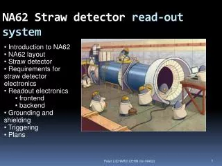
Detector R&D for Mu on Ch amber Anand K. Dubey For VECC group. CBM Muon detector requirements:. Main issues: The first plane(s) has a high density of tracks -- detector should be able to cope up with high rate. ~ 10 MHz/cm 2 good position resolution

E N D
Detector R&D for Muon Chamber Anand K. Dubey For VECC group
CBM Muon detector requirements: • Main issues: • The first plane(s) has a high density of tracks • -- detector should be able to cope up with • high rate. ~ 10 MHz/cm2 • good position resolution • Should be radiation resistant • Large area detector – modular arrangement • suitable options: • micropattern gas detectors such as GEMs, • Micromegas, and THGEMs.
MUCH R&D so far: we have assembled and tested double and triple GEM prototypes based on 10 cm x 10 cm GEM foils. Optimize the operating conditions with 10 cm x 10 cm. the detector should have: -- a high charged particle efficiency(>90%) -- a good dynamic range. -- a reasonable cluster size for tracking. -- a good rate handling capability In future we would like to go to 30 cm x 30 and later to foils with larger dimensions.
Schematic of prototype GEM chamber assembly CERN made GEM foils obtained from Area: 10cm x 10cm Readout PCB GEMS 1 2 3 Drift gap: ~7mm Induction gap: 1.5mm Transfer gap: 1mm Drift plane (inner side copper plated) In the next prototypes we have an O-ring on the perspex frame In order to facilitate quick changing on GEMs if needed. 12 x cm 12 cm x 10 mm
Testing of GEM chambers @GSI At the SIS 18 beam line using proton beams of 2.5 GeV/c Aim being : -- to test the response of the detector to charged particles. -- efficiency, cluster size, gain uniformity, rate capability -- testing with actual electronics for CBM : nXYTER -- testing with the actual DAQ -- Aug08-- first successful test with n-XYTER(with 64 channels bonded ) + GEM was performed. MIP spectra for 2GEMs and 3 GEMs were obtained. -- Aug-Sep 09, In 2009 a fuller version of nXYTER with all the 128 channels bonded was available. this offered a better configuration for efficiency estimation and also for cluster size estimation.
Readout Board for Test beam Aug-Sep 09 Two triple GEM chambers were fabricated : det 01 – with two different pad sizes(shown below) det02 -- same size pads but with larger induction gap Inside view Outside view Inside view
Aug-Sep09 test (with 2.3 GeV/c protons) pulse height spectra Correlation between GEM1 and GEM2
ADC distribution of main cell and variation with HV 4 fold increase in ADC for a deltaV(GEM) increase by 50V
Determining the Efficiency Time difference between trigger(aux) and GEM ROC Procedure: Get the GEM pads hit in 900-1200 nsec after last Aux. Offset + drift time Using STS Hits
Efficiency with time Eff_66 HV= 3650 HV= 3750 Looks like the detector takes some time to become stable, -- need more online investigations 95 % efficiency has been achieved by 3 GEM chamber used by the CMS upgrade group. The chamber tested in June2010. next slide
10 cm x 10 cm GEMs Readout: Strips of 0.8 mm pitch so 95 % efficiency is achievable things can be complicated with pads, -- one such large GEM with pad readout was tested in June 2010 -- analysis is still underway Preliminary Slides from Stefano Colaresi – CMS upgrade, RD51 miniweek, 19-07-2010
Cosmic Ray test setup at VECC • Setup for detector efficiency: • 1. Detector+Ortec preamp+amp • Using MANAS coupled to • PCI CFD card • 3. Using Aux + nXYTER
Results with MANAS GEM signal connected to Channel 56 of FEE (MANAS) Pedestal 64 channels for 4 MANAS No of triggers( from 3 FOLD) = 187 Entries =158 => 85% After pedestal subtraction -ADC of Channel 56
3GEM Pulse height distribution at different HV with MANAS HV=3600 HV =3550 (Vgem=394 V) HV 3650 HV 3700 HV =3725(Vgem=413) The MIP peak shifts with HV
Top copper Readout PCBS for Test beam 2010 GND Plane Inner 2 GND Plane Top copper Inner 1 Pad area- 67*73 Sq mm For 3mm. For 4mm - 88*97 sq mm Bottom copper GND Plane • Main Features : • Both 3 and 4mm square pad sizes • Not Staggered (‘09 test beam module) • Symmetric Square Pads • Multi Layers ( 4) with GND Planes • Signal Tracks are distributed in 3 planes • Reduce the capacitance • Track to Track spacing increases • Reduce Cross talk • Blind Vias for gas integrity • Gnd Tracks between Signal Tracks Bottom copper Connectors for FEBs Connector with resistors
Placement of ROC Boards ROC stack ROC stack Tracking station plane 3mt (approx) 2m Physics With FAIR: Indian Perspective, Susanta K Pal
-- CMS upgrade, slides from A. Sharma, RD51 miniweek,19-07-2010 (1)
CMS Prototype GEM - Stack Profile ~ 15 mm (2)
CMS Prototype GEM - Test BoxLarge Drift Electrode Sample under test Jean-Paul Chatelain (3)
MUCH PCB design Top copper Inner 1 Inner-2 Bottom Copper • Modular Approach 2.6 mm square pads • Pads arranged in one block of 32*8=256. • Connected to 300 pin connector. • Tracks - shorter and not closer . • can be easily duplicated for bigger sizes. • 40 such FEE Boards for One Slat of 1mt. Length.. • Each block read by 1 FEB with 2/4 n-XYTERs ( 128/64 Channels) • FEBs can be mounted horizontal or vertical Blind vias (red ) to inner layer Blind vias from inner layers( blue) Physics With FAIR: Indian Perspective, Susanta K Pal
Conceptual sketch of Triple GEM chamber module 1 mt Gas out HV 10cm Gas in To be decided LV connector • Segmented LV power line/power plane on Detector PCB • each power line is feeding 5-FEBs • ground plane of LV line is in other layer of PCB 40 FEBs in one module in 1mt slat with about 10240 channels Physics With FAIR: Indian Perspective, Susanta K Pal
Chamber PCB 4 sq mm pads. 32*32 Array(1024 pads). PCB active area is 135mm *135 mm. Read by 2 chip FEB(256 channels) Basic block=32*8 array. Track lengths are short. Top side Inner 1 layer Bottom side GND Plane Inner 2 layer Sa SAMTEC-300 Pin connectors 2chipFEBs
Chamber PCB with 4 FEBs Bottom view of FEB FEB 2 FEB 3 FEB 1 FEB 4 Top view with 4 sq mm pads Bottom view –Connectors for FEBs
2 CHIP FEB –PCB 8 layer PCB. Size =111mm*31mm No scooping for N XYTER on the PCB. Regulators - on top copper. Filter capacitors- on bottom copper N-XYTER ADC 300 Pin SAMTEC Connector ROC Connector Top Copper Bottom copper
SUMMARY • Double and Triple GEMs have been assembled at VECC. • Tests performed with radioactive sources as well with • proton beams at GSI. • Test with proton beams: Double GEM and triple GEMs • coupled to the first prototype of n-XYTER readout chip. • – preliminary response looked encouraging. • -- charged particle detection efficiency needs to be still higher. • investigations underway, using tests with cosmic rays. • Next test beam: two chambers of 3x3 sq. mm 4x4 sq. mm chamber • would require 8 FEBs. • Several layout s of the actual design of the Muon Chamber • under discussion. Actual size of large GEMs for the final chamber • under consideration –- keeping informed with the CMS upgrade • involving triple GEMs.
Thanks For Your Attention
Readout plane-bottom Copper ERNI Part no 114805 4 No –68Pins 68 Pin connectors for FEB 1nXGen Resistors for input Protection 68 Pin connectors for FEB 1nXGen
Triple GEM: Test with Fe-55 3GEM: Gain vs. Vgem