Download
1 / 43
430 likes | 611 Views
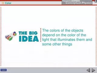
In the recent lecture: Color Science Color Models In Images Color Models In Videos. Color Science. Light and Spectra Light is an electromagnetic (EM) wave Visible light ranges from 400nm to 700nm

E N D
In the recent lecture: • Color Science • Color Models In Images • Color Models In Videos
Color Science Light and Spectra • Light is an electromagnetic (EM) wave • Visible light ranges from 400nm to 700nm • Spectral Power Distribution (SPD), or spectrum, E(λ), shows the relative amount of light energy at each wavelength λ.
Color Science Light and Spectra • Spectral Power Distribution (SPD), or spectrum, E(λ), shows the relative amount of light energy at each wavelength λ.
Color Science Human Vision Retina consists of an array of rods and three kinds of cones Rods are for night vision Cones are for color vision Three kinds of cones: L-cone: most sensitive to Red light M-cone: most sensitive to Green light S-cone: most sensitive to Blue light
Color Science Spectral Sensitivity of the Eye • The eye is most sensitive to light in the middle of the visible spectrum. • The response in each color channel in the eye is proportional to the number of neurons ring. – Red Receptor Sensitivity qR(λ) – Green Receptor Sensitivity qG(λ) – Blue Receptor Sensitivity qB(λ)
Color Science The Blue receptor sensitivity is not shown to scale because it is much smaller than the curves for Red or Green. • Luminous-efficiency function V (λ)overall sensitivity: • is formed by the sum of the response curves for Red, Green and Blue
Color Science Light and Spectra • Total response on each channel is given by: – R = ∫ E(λ) qR(λ) dλ – G = ∫ E(λ) qG(λ) dλ – B = ∫ E(λ) qB(λ) dλ
Color Science Image Formation • Light from the illuminant (light source) with SPD E(λ) impinges on a surface, with surface spectral reflectance function S(λ), is reflected, and then is filtered by the eye's cone functions q(λ). • The color signal C(λ), is defined by C(λ) = E(λ) S(λ) • Total response on each channel is now given by R = ∫ E(λ) S(λ) qR(λ) dλ = ∫ C(λ) qR(λ) dλ G = ∫ E(λ) S(λ) qG(λ) dλ = ∫ C(λ) qG(λ) dλ B = ∫ E(λ) S(λ) qB(λ) dλ = ∫ C(λ) qB(λ) dλ
Color Science Camera system • Camera systems are made in a similar fashion; a studio-quality camera has three signals produced at each pixel location (corresponding to a retinal position). • Analog signals are converted to digital, truncated to integers, and stored. If the precision used is 8-bit, then the maximum value for any of R, G, B is 255, and the minimum is 0. • However, the light entering the eye of the computer user is that which is emitted by the screen — the screen is essentially a self-luminous source. Therefore we need to know the light E(λ) entering the eye.
Color Science Gamma Correction • The light emitted is in fact roughly proportional to the voltage raised to a power; this power is called gamma, with symbol γ . (a) Thus, if the file value in the red channel is R, the screen emits light proportional to Rγ, with SPD equal to that of the red phosphor paint on the screen that is the target of the red channel electron gun. The value of gamma is around 2.2 . (b) It is customary to append a prime to signals that are gamma-corrected by raising to the power (1/ γ) before transmission. Thus we arrive at linear signals: R R\ = R1/ γ (R\)γ R
Color Science Gamma Correction (a): Effect of CRT on light emitted from screen (voltage is normalized to range 0..1). (b): Gamma correction of signal.
Color Science Gamma Correction Homework: 1-Write procedure to apply gamma correction on a low color range image. 2-show how you could apply eq. 4.5 In digital image case. Without Gamma Correction With Gamma Correction
Color Science Color-Matching Functions • The particular set of three basic lights R,G,B used in this experiment is called the set of color primaries. • Color-matching experiment: To match a given color, a subject is asked to separately adjust the brightness of the three primaries using a set of controls until the resulting spot of light matches most closely with the desired color. • Colorimeter: A device for carrying out the color-matching experiment • The amounts of R, G, and B the subject selects to match each single-wavelength light forms the color-matching curves. • Color primaries: peaks at 440nm, 545nm and 580nm
Color Science The negative part of the curve indicates that some color cannot be reproduced by linear combination of the primaries. So for such color, one or more primary lights has to be shifted from one side to other.
Color Science CIE Chromaticity Diagram • In 1931, the CIE (Commission International de L'Eclairage, or International Commission on Illumination) defined three standard primaries (X, Y, Z). • The Y primary was intentionally chosen to be identical to the luminous-efficiency function of human eyes.
Color Science CIE Chromaticity Diagram CIE RGB color=matching functions ,, CIE standard color=matching functions
Color Science CIE Chromaticity Diagram This figure shows the amounts of X, Y, Z needed to exactly reproduce any visible color.
Color Science CIE Chromaticity Diagram
Color Science • Color Monitor Specifications • Color monitors are specified in part by the white point chromaticity that is desired if the RGB electron guns are all activated at their highest value (1.0, if we normalize to [0,1]). • We want the monitor to display a specified white when R\=G\=B\=1. • There are several monitor specifications in current use (Table 4.1).
Color Science XYZ to RGB Transform • Now the 3 × 3 transform matrix from XYZ to RGB is taken to be T = M D • even for points other than the white point: • For the SMPTE specification, we arrive at: • Q: How we transform among XYZ and • RGB with gamma correction Homework: 1- Find inverse matrix of the current 3 × 3 matrix 2-show how you could apply In real digital image both forward and backward. 3- Find Transform matrix For the NTSC specification for both forward and backward
Color Science Homework Solution: 1- Find inverse matrix of the current 3 × 3 matrix 2-show how you could apply In real digital image both forward and backward. 3- Find Transform matrix For the NTSC specification for both forward and backward
Color Models in image More Color Coordinate Schemes • Beware: gamma correction or not is usually ignored. • Schemes include: • CMY—Cyan (C), Magenta (M ) and Yellow (Y ) color model; • HSL — Hue, Saturation and Lightness; • HSV — Hue, Saturation and Value; • HSI — Hue, Saturation and Intensity; • HCI — C = Chroma • HVC — V= Value • HSD — D = Darkness Homework: Show how we could use these color transforms in the following image processing fields: 1- Enhancement, 2-Segmentation , 3-Classification
Color Models In Images RGB Color Model (Additive for CRT Display) • We expect to be able to use 8 bits per color channel for color that is accurate enough. • However, in fact it have to use about 12 bits per channel to avoid an aliasing effect in dark image areas — contour bands that result from gamma correction. • For images produced from computer graphics, we store integers proportional to intensity in the frame buffer. So should have a gamma correction LUT between the frame buffer and the CRT. • If gamma correction is applied to floats before quantizing to integers, before storage in the frame buffer, then in fact we can use only 8 bits per channel and still avoid contouring artifacts.
Color Models In Images CMY Color Model (Subtractive for Printing) • Cyan, Magenta, and Yellow (CMY) are complementary colors of RGB. They can be used as Subtractive Primaries. • CMY model is mostly used in printing devices where the color pigments on the paper absorb certain colors (e.g., no red light reflected from cyan ink).
Color Models In Images Conversion between RGB and CMY • For Example, convert White from (1, 1, 1) in RGB to (0, 0, 0) in CMY. .
Color Models In Images Conversion between RGB and CMY • Sometimes, an alternative CMYK model (K stands for Black) is used in color printing (e.g., to produce darker black than simply mixing CMY). Homework: Why we use CMY ink instead of using RGB ink in color printers?
Color Models In Video Video Color Transforms • Largely derive from older analog methods of coding color for TV. Luminance is separated from color information. • For example, a matrix transform method similar to Eq. (4.9) called YIQ is used to transmit TV signals in North America and Japan. • This coding also makes its way into VHS video tape coding in these countries since video tape technologies also use YIQ. • In Europe, video tape uses the PAL or SECAM codings, which are based on TV that uses a matrix transform called YUV. • Finally, digital video mostly uses a matrix transform called YCbCr that is closely related to YUV
Color Models In Video YUV Color Transform • Initially, for PAL analog video, it is now also used in CCIR 601 standard for digital video • Y (luminance) is the CIE Y primary. Y = 0.299R + 0.587G + 0.114B ……………. (1) • Chrominance is defined as the difference between a color and a reference white at the same luminance. It can be represented by U and V -- the color differences. U = B – Y …………………… (2)V = R – Y …………………… (3) • If b/w image, then U = V = 0. No chrominance! • ** In actual PAL implementation: U = 0.492 (B - Y) V = 0.877 (R - Y) Homework: Find Backward transform. R = Y + V G = Y - (0.195 × U) - (0.509 × V) B = Y + U
Color Models In Video YIQ Color Transform • YIQ is used in NTSC color TV broadcasting, it is downward compatible with B/W TV where only Y is used. • Although U and V nicely define the color differences, they do not align with the desired human perceptual color sensitivities. In NTSC, I and Q are used instead. • I is the orange-blue axis, Q is the purple-green axis. I and Q axes are scaled and rotated R - Y and B - Y (by 33 degrees clockwise). I = 0.877(R - Y) cos 33 - 0.492(B - Y) sin 33 Q = 0.877(R - Y) sin 33 + 0.492(B - Y) cos 33 • Namely, • I = 0.736(R - Y) - 0.268(B - Y) = 0.596R - 0.275G - 0.321B Q = 0.478(R - Y) + 0.413(B - Y) = 0.212R - 0.523G + 0.311B R = G = B = Homework: Find Backward transform.
Color Models In Video YUV Color Transform Y U V Eye is most sensitive to Y. In PAL, 5.5 MHz is allocated to Y, 1.8 MHz each to U and V
Color Models In Video YIQ Color Transform Y I Q Eye is most sensitive to Y. In PAL, 5.5 MHz is allocated to Y, 1.8 MHz each to U and V
Color Models In Video YCbCr Color Transform • The YCbCr model is closely related to the YUV, it is a scaled and shifted YUV. Cb = (B - Y) / 1.772 + 0.5 Cr = (R - Y) / 1.402 + 0.5 • The chrominance values in YCbCr are always in the range of 0 to 1. • YCbCr is used in JPEG and MPEG. Homework: Find Backward transform. R = G = B =
Color Models In Video YUV Transform Matrix
Color Models In Video YIQ Transform Matrix
Color Models In Video YCbCr Transform Matrix