Download
1 / 23
250 likes | 436 Views
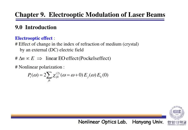
Chapter 9. Electrooptic Modulation of Laser Beams. 9.0 Introduction Electrooptic effect : # Effect of change in the index of refraction of medium (crystal) by an external (DC) electric field. #. # Nonlinear polarization :. 9.1 Electrooptic Effect. Index Ellipsoid.

E N D
Chapter 9. Electrooptic Modulation of Laser Beams 9.0 Introduction Electrooptic effect : # Effect of change in the index of refraction of medium (crystal) by an external (DC) electric field # # Nonlinear polarization :
9.1 Electrooptic Effect Index Ellipsoid Displacement current : Energy density : : for the principal axes Put, : Index ellipsoid
General expression of index ellipsoid : impermeability tensor element where, Energy density : Put, Put,
Impermeability : Linear EO Quadratic EO Kleinman symmetric medium : (9.1-3) : Electrooptic tensor (element) where,
(9.1-3) ex) E=0,
Example) EO effect in KH2PO4 (KDP ; negative uniaxial crystal, symmetry group) When the electric filed is applied along the z-axis, the equation of the index ellipsoid is given by The Sij matrix is Report : Summary (pp. 333-339) For the principal axis, Condition for nontrivial solution (eigenvalue equation) :
2) For S’’ Similarly, 3) For S’’’ New principal axes : The equation of the index ellipsoid in the new principal coordinate system :
9.2 Electrooptic Retardation For a wave propagating along the z-direction, the equation of the index ellipsoid is Assuming, Field components polarized along x’ and y’ propagate as
Phase difference at the output plane z=l between the two components (Retardation) : The retardation can also be written as (Halfwave retardation voltage)
9.3 Electrooptic Amplitude Modulation or, using the complex amplitude notation
The ratio of the output intensity to the input : : amplitude modulation
9.4 Phase Modulation of Light Electric field does not change the state of polarization, but merely changes the output phase by If the bias field is sinusoidal ; where, : Phase modulation index : side band (harmonics)
9.5 Transverse Electrooptic Modulators Longitudinal mode of modulation : E field is applied along the direction of light propagation Transverse mode of modulation : E field is applied normal to the direction of light propagation # Transverse mode is more desirable : 1) Electrodes do not interfere with the optical beam 2) Retardation (being proportional to the crystal length) can be increased by use of longer crystal 3) Can make the crystal have the function of l/4 plate
9.6 High-Frequency Modulation Considerations If Rs > (woC)-1, most of the modulation voltage drop is across Rs wasted ! Solution : LC resonance circuit + Shunting resistance, RL >>Rs LC parallel circuit, Total impedance : At the resonance [w=w0=1/(LC)1/2],
Maximum bandwidth : Required power for the peak retardation Gm : where, : cross-sectional area of the crystal normal to l
Transit-Time Limitation to High-Frequency Electrooptic Modulation (9.2-4) But, if the field E changes appreciably during the transit time through the crystal, Taking e(t) as a sinusoid ; Phase change during the transit-time,td=nl/c Practically, in order to obtain |r|=0.9, Reduction Factor, r (Fig. 11-17) Ex) KDP, n=1.5, l=1cm, : Peak retardation where,
Traveling wave Modulators : matching the phase velocities of the optical and modulation fields by applying the modulation signal in the form of a traveling wave Consider an element of the optical wavefront that enters the crystal at z=0 at time t The retardation exercised by this element is given by
The traveling modulation field : : Peak retardation where, Reduction factor : # c/n=cm r = 1 # Maximum modualtion frequency (|r|=0.9) :
9.7 Electrooptic Beam Deflection Deflection angle inside the crystal ( ) External deflection angle (By Snell’s law)
Double-prism KDP beam deflector Number of resolvable spots, N (for a Gaussian beam) : # (9.2-7)