1 / 0

Chapter 8 Wireless Networking

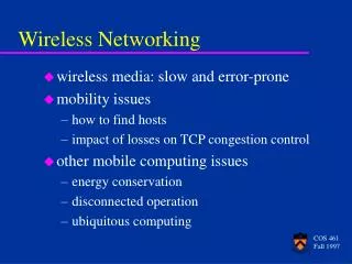
CIS 1140 Network Fundamentals. Chapter 8 Wireless Networking. Collected and Compiled By JD Willard MCSE, MCSA, Network+, Microsoft IT Academy Administrator Computer Information Systems Instructor Albany Technical College. Attention: Accessing Demos. This course presents many demos.

trisha
Download Presentation

Chapter 8 Wireless Networking

An Image/Link below is provided (as is) to download presentation Download Policy: Content on the Website is provided to you AS IS for your information and personal use and may not be sold / licensed / shared on other websites without getting consent from its author. Content is provided to you AS IS for your information and personal use only. Download presentation by click this link. While downloading, if for some reason you are not able to download a presentation, the publisher may have deleted the file from their server. During download, if you can't get a presentation, the file might be deleted by the publisher.

E N D

Presentation Transcript


  1. CIS 1140 Network Fundamentals

    Chapter 8 Wireless Networking

    Collected and Compiled By JD Willard MCSE, MCSA, Network+, Microsoft IT Academy Administrator Computer Information Systems Instructor Albany Technical College
  2. Attention: Accessing Demos This course presents many demos. The Demosrequire that you be logged in to the Virtual Technical College web site when you click on them to run. To access and log in to the Virtual Technical College web site: To access the site type www.vtc.com in the url window Log in using the username: CIS 1140 or ATCStudent1 *Enter the password: student If you should click on the demo link and you get an Access Denied it is because you have not logged in to vtc.com or you need to log out and log back in. *Remember that passwords are case sensitive so enter it in all lower case letters.
  3. Objectives Explain how nodes exchange wireless signals Identify potential obstacles to successful wireless transmission and their repercussions, such as interference and reflection Understand WLAN (wireless LAN) architecture Specify the characteristics of popular WLAN transmission methods, including 802.11 a/b/g/n Install and configure wireless access points and their clients Describe wireless MAN and WAN technologies, including 802.16 and satellite communications Wireless Basics Demo
  4. Wireless Transmission Networks that transmit signals through the atmosphere via infrared or RF waves are known as wireless networks or wireless LANs (WLANs) Computers communicate using standard networking protocols, but without the use of cabling to connect devices The computers transmit data by means of wireless signals produced by infrared (requiring equipment to be in a direct line of sight) or radio waves Wireless networks require installation of NICs with built-in antennas and uses access points as hubs Wireless networks use the 2.4-2.4835 GHz frequency range Introduction Demo Wireless Hardware Overview Demo
  5. The Wireless Spectrum Continuum of electromagnetic waves Data, voice communication Arranged by frequencies Lowest to highest Spans 9 KHz and 300 GHz Wireless services associated with one area Most cordless telephones and many wireless LANs use frequencies around 2.4 GHz. FCC oversees United States frequencies ITU oversees international frequencies Air signals propagate across borders
  6. Characteristics of Wireless Transmission Wireless signals originate from electrical current traveling along a conductor The signal travels from the transmitter to an antenna, which emits the signal, as a series of electromagnetic waves, to the atmosphere The signal propagates through the air until it reaches its destination At the destination, another antenna accepts the signal, and a receiver converts it back to current
  7. Characteristics of Wireless Transmission Similarities with wired Layer 3 and higher protocols Signal origination From electrical current, travel along conductor Differences from wired Signal transmission No fixed path, guidance Antenna Signal transmission and reception Same frequency required on each antenna Share same channel Wireless Vs Wired Networks Demo
  8. Characteristics of Wireless Transmission Wireless transmission and reception
  9. Antennas Radiation pattern describes relative strength over three-dimensional area of all electromagnetic energy the antenna sends or receives Directional antenna issues wireless signals along a single direction Omnidirectional antenna issues and receives wireless signals with equal strength and clarity in all directions Range: geographical area an antenna or wireless system can reach, generally about 100m Antennas Demo
  10. Multipath signal propagation Signal Propagation LOS (line-of-sight) Signal travels In straight line, directly from transmitter to receiver Obstacles affect signal travel Pass through them Absorb into them Subject signal to three phenomena Reflection: bounce back to source Diffraction: splits into secondary waves Scattering: diffusion in multiple different directions Multipath signals Wireless signals follow different paths to destination Caused by reflection, diffraction, scattering Advantage Better chance of reaching destination Disadvantage Signal delay
  11. Signal Degradation Fading Change in signal strength Electromagnetic energy scattered, reflected, diffracted Attenuation Signal weakens Moving away from transmission antenna Correcting signal attenuation Amplify (analog), repeat (digital) Noise Significant problem No wireless conduit, shielding
  12. Frequency Ranges 2.4-GHz band (older) Frequency range: 2.4–2.4835 GHz 11 unlicensed communications channels Susceptible to interference Unlicensed No FCC registration required 5-GHz band (newer) Frequency bands 5.1 GHz, 5.3 GHz, 5.4 GHz, 5.8 GHz 24 unlicensed bands, each 20 MHz wide Used by weather, military radar communications
  13. Narrowband, Broadband, and Spread Spectrum Signals Narrowband: transmitter concentrates signal energy at single frequency or in very small range of frequencies Broadband: uses relatively wide band of wireless spectrum Offers higher throughputs than narrowband Spread spectrum: use of multiple frequencies to transmit a signal which offers security FHSS (frequency hopping spread spectrum) Signal jumps between several different frequencies within band Synchronization pattern known only to channel’s receiver, transmitter DSSS (direct-sequence spread spectrum) Signal’s bits distributed over entire frequency band at once Each bit coded Receiver reassembles original signal upon receiving bits Wireless Transmission Methods Demo
  14. Fixed versus Mobile Fixed communications wireless systems Transmitter, receiver locations do not move Transmitting antenna focuses energy directly toward receiving antenna Point-to-point link results Advantage No wasted energy issuing signals More energy used for signal itself Mobile communications wireless systems Receiver located anywhere within transmitter’s range Receiver can roam
  15. Wireless LAN (WLAN) Architecture Ad hoc WLAN Wireless nodes transmit directly to each other Use wireless NICs No intervening connectivity device Poor performance Many spread out users, obstacles block signals Access point (AP) Accepts wireless signals from multiple nodes Retransmits signals to network Base stations, wireless routers, wireless gateways An ad-hoc WLAN Wireless Topologies Demo
  16. Wireless LAN Architecture Infrastructure Mode WLAN Stations communicate with access point Not directly with each other Access point requires sufficient power, strategic placement WLAN may include several access points Dependent upon number of stations Maximum number varies: 10-100 An infrastructure WLAN
  17. Wireless LAN Architecture A WAP works as a wireless bridge to connect the wireless nodes to the wired network A WAP must be strategically located so that stations can communicate with it The maximum number of stations each access point can server varies from 10 to 100 Stations must stay within the range of a WAP, generally 300 feet or 100 meters Wireless LAN interconnection Wireless Access Points Demo
  18. WLAN Architecture Mobile networking allows roaming wireless nodes Range dependent upon wireless access method, equipment manufacturer, office environment Access point range: 300 feet maximum Can connect two separate LANs Fixed link, directional antennas between two access points Allows access points 1000 feet apart Support for same protocols, operating systems as wired LANs Ensures compatibility Wireless LAN interconnection
  19. 802.11 WLANs Wireless technology standard Describes unique functions Physical and Data Link layers Differences Specified signaling methods, geographic ranges, frequency usages Developed by IEEE’s 802.11 committee Wi-Fi (wireless fidelity) standards 802.11b, 802.11a, 802.11g, 802.11n (draft) Share characteristics Half-duplexing, access method, frame format Radio Frequency Networking Demo Wireless Networking StandardsDemo
  20. Wireless Networks: 802.11 A WLAN with multiple access points
  21. Access Method 802.11 MAC services Append 48-bit (6-byte) physical addresses to frame Identifies source, destination Same physical addressing scheme as 802.3 Allows easy combination Wireless devices Not designed for simultaneous transmit, receive Cannot quickly detect collisions Use different access method CSMA/CA (Carrier Sense Multiple Access with Collision Avoidance) Minimizes collision potential Uses ACK packets to verify every transmission Requires more overhead than 802.3 Real throughput less than theoretical maximum RTS/CTS (Request to Send/Clear to Send) protocol Optional Ensure packets not inhibited by other transmissions Efficient for large transmission packets Further decreases overall 802.11 efficiency
  22. A network with a single BSS Association Packet exchanged between computer, access point Gain Internet access Scanning Surveying surroundings for access point Active scanning transmits special frame Probe Passive scanning listens for special signal Beacon fame SSID (service set identifier) Unique character string used to identify an access point In beacon fame information Configured in access point Better security, easier network management BSS (basic service set) Station groups sharing access point BSSID (basic service set identifier) Station group identifier
  23. Association ESS (extended service set) Access point group connecting same LAN Share ESSID (extended service set identifier) Allows roaming Station moving from one BSS to another without losing connectivity Several access points detected Select strongest signal, lowest error rate Poses security risk Powerful, rogue access point ESS with several authorized access points Must allow station association with any access point While maintaining network connectivity Reassociation Mobile user moves from one access point’s range into another’s range Occurs by simply moving, high error rate Stations’ scanning feature Used to automatically balance transmission loads Between access points A network with multiple BSSs forming an ESS
  24. Frames 802.11 networks overhead ACKs, probes, beacons 802.11 specifies MAC sublayer frame type Multiple frame type groups Control: association and reassociation Probe, beacon frames Management: medium access, data delivery ACK and RTS/CTS frames Data: carry data sent between stations 802.11 data frame overhead Four address fields Source address, transmitter address, receiver address, destination address Sequence Control field How large packet fragmented Frame Control field Wi-Fi share MAC sublayer characteristics Wi-Fi differ in modulation methods, frequency, usage, ranges Basic 802.11 data frame
  25. 802.11b 802.11b also know as Wi-Fi for Wireless Fidelity The oldest and least expensive wireless standard Compatible with 802.11g and being replace by 802.11g Uses Direct Sequence Spread Spectrum signaling in the 2.4-GHz band Theoretical maximum throughput of 11Mbps; actual throughput typically around 5Mbps Nodes must stay within 100 meters of an access point 802.11b Wireless Local Area Networks (WLANs) support three non-overlapping or non-interfering channels that can be used in a single area The Wireless Access Points or bridges must use non-adjacent, non-overlapping radio channels to prevent interference from the adjacent bridge or Access Point When using multiple bridges to cover a large area, you should ensure that the channels are configured in such a way that there is no overlapping 802.11b Demo
  26. 802.11a Released after 802.11b 802.11a differs from 802.11b and 802.11g in that it uses multiple frequency bands in the 5GHz range Not congested like 2.4-GHz band Lower interference, requires more transmit power Provides a maximum theoretical throughput of 54Mbps, though its effective throughput falls generally between 11 and 18Mbps Attributable to higher frequencies, unique modulating data method, more available bandwidth The average geographic range for an 802.11a antenna is 20 meters, or approximately 66 feet As a result, 802.11a networks require a greater density of access points between the wire-bound LAN and wireless clients to cover the same distance that 802.11b networks cover More expensive than either 802.11b or 802.11g Not compatible with either 802.11b and 802.11g 802.11a Demo
  27. 802.11g 802.11g is just as affordable as 802.11b A maximum theoretical throughput of 54Mbps through different encoding techniques The effective throughput ranges generally from 20 to 25 Mbps Its geographic range is 100 meters or 328 feet 802.11b and 802.11g NICs and WAPs can be mixed into the same network 802.11g uses the 2.4-GHz frequency band making it compatible with 802.11b networks 802.11g Demo
  28. 802.11n Draft: expected ratification in late 2009 Manufacturers Selling 802.11n-compatible transceivers Primary goal Wireless standard providing much higher effective throughput Maximum throughput: 600 Mbps Threat to Fast Ethernet Backward compatible with 802.11a, b, g standards May use either the 2.4-GHz or 5-GHz frequency range. Compared with 802.11a, 802.11g Same data modulation techniques Compared with three 802.11 standards Manages frames, channels, encoding differently Allows high throughput 802.11n Demo
  29. 802.11n 802.11n access point with three antennas MIMO (multiple input-multiple output) Multiple access point antennas may issue signal to one or more receivers Increases network’s throughput, access point’s range Channel bonding Two adjacent 20-MHz channels bonded to make 40-MHz channel Doubles the bandwidth available in single 20-MHz channel Bandwidth reserved as buffers assigned to carry data Higher modulation rates Single channel subdivided into multiple, smaller channels More efficient use of smaller channels Different encoding methods
  30. Aggregated 802.11n frame 802.11n Maximum throughput dependencies Number, type of strategies used 2.4-GHz or 5-GHz band Actual throughput: 65 to 600 Mbps Backward compatible Not all 802.11n features work Recommendation Use 802.11n-compatible devices Frame aggregation Combine multiple frames into one larger frame Advantage: reduces overhead
  31. Bluetooth Bluetooth is a short-range radio technology aimed at creating a very easy to set up, small in nature, wireless network. It’s normally used for mobile devices sharing a close proximity. Wireless mice and keyboards commonly use Bluetooth. Ericson’s original goals Wireless technology compatible with multiple devices Require little power Cover short ranges Aim of Bluetooth Special Interest Group (SIG) Refine and standardize technology Result: Bluetooth Mobile wireless networking standard using FHSS (frequency hopping spread spectrum) RF signaling in 2.4-GHz band Version 1.1 Maximum theoretical throughput: 1 Mbps Effective throughput: 723 Kbps 10 meter node difference Designed for PANs (personal area networks) Version 2.0 (2004) Different encoding schemes 2.1-Mbps throughput communicating nodes can be as far as 30 meters apart Usage: cellular telephones, phone headsets, computer peripherals, PDAs Overview of Bluetooth Demo
  32. Summary of WLAN Standards Wireless standards
  33. Implementing a WLAN Designing a small WLAN Home, small office Formation of larger, enterprise-wide WANs Installing and configuring access points and clients Implementation pitfalls Avoidance Material applies to 802.11b and 802.11g Most popular
  34. Determining the Design One access point Combine with switching, routing functions Connects wireless clients to LAN Acts as Internet gateway Access point WLAN placement considerations Typical distances between access point and client Obstacles Type, number between access point and clients
  35. Determining the Design Larger WLANs Systematic approach to access point placement Site survey Assesses client requirements, facility characteristics, coverage areas Determines access point arrangement ensuring reliable wireless connectivity Within given area Proposes access point testing Testing wireless access from farthest corners Install access points Must belong to same ESS, share ESSID Enterprise-wide WLAN design considerations How wireless LAN portions will integrate with wired portions Enterprise-wide WLAN Site Survey & Design Demo
  36. Configuring Wireless Connectivity Devices Netgear WGR614 (v7) Popular, low-cost access point Four switch ports, routing capabilities Supports 802.11b, 802.11g transmission Configuration steps on other small wireless connectivity devices Differ somewhat Follow similar process, modify same variables Configure WAP Demo
  37. The Netgear router Basic Settings page
  38. Netgearrouter Wireless Settings page
  39. The Netgear router Advanced Wireless Settings page
  40. The Netgear router LAN IP Setup page
  41. The Netgear router Router Status page
  42. Wireless Router Re-Configuration If something goes awry during your wireless router configuration, you can force all of the variables you changed to be reset. Wireless routers feature a reset button on their back panel. To reset the wireless router, first unplug it. Then, using the end of a paperclip, depress the reset button while you plug it in. Continue holding down the button for at least 30 seconds (this time period varies among manufacturers; check your wireless router’s documentation for the duration yours requires). At the end of this period, the wireless router’s values will be reset to the manufacturer’s defaults.
  43. Configuring Wireless Clients Configuration varies from one client type to another Windows XP client WLAN configuration Use graphical interface Linux and UNIX clients wireless interface configuration Use graphical interface iwconfigis a command-line function for viewing and setting wireless interface parameters and it is common to nearly all versions of Linux and UNIX
  44. Configuring Wireless Clients Windows XP Wireless network properties dialog box Windows XP Wireless Network Connection Properties dialog box Configure Wireless client Demo
  45. Configuring Wireless Clients Output from iwconfig command
  46. Avoiding Pitfalls Access point versus client configurations SSID mismatch Incorrect encryption Incorrect channel, frequency Standard mismatch (802.11 a/b/g/n) Incorrect antenna placement Verify client within 330 feet Interference Because wireless signals cannot depend on a conduit or shielding to protect them from extraneous EMI, they are more vulnerable to noise. The extent of interference depends partly on the density of signals within a geographical area. If intermittent and difficult-to-diagnose wireless communication errors occur, interference might be the culprit. Check for EMI sources
  47. Wireless WANs and Internet Access Wireless broadband Latest wireless WAN technologies Specifically designed for: High-throughput, long-distance digital data exchange
  48. 802.11 Internet Access Access points: 802.11b or 802.11g access methods Hot spots Places with publicly available wireless Internet access Free or subscription Hot spot subscription Internet access Log on via Web page Client software managing client’s connection Network log on, secure data exchange Added security: accept connection based on MAC address Accept user’s connection based on MAC address
  49. 802.16 (WiMAX) Internet Access WiMAX (Worldwide Interoperability for Microwave Access) Current version: 802.16e (2005) Improved mobility, QoS characteristics Digital voice signals, mobile phone users Functions in 2 and 66 GHz range Licensed, nonlicensed frequencies line-of-sight paths between antennas Throughput potential maximized Non-line-of-sight paths Exchange signals with multiple stations at once Two distinct advantages over Wi-Fi Much greater throughput (70 Mbps) Much farther range (30 miles) Appropriate for MANs and WANs Highest throughput achieved over shortest distances between transceivers Possible uses Alternative to DSL, broadband cable Well suited to rural users Internet access to mobile computerized devices Residential homes
  50. Residential WiMAX Installation In residential WiMAX the carrier installs a small antenna on the homeowner’s roof or chimney or even inside the house. This antenna is connected to a device similar to a cable or DSL modem for clients to access the LAN. The connectivity device could be incorporated along with the antenna in the same housing or might be separate. If separate, the device typically attaches to the antenna with coaxial cable. It’s often combined with a router. The homeowner’s antenna communicates in a non-line-of-sight fashion with the service provider’s antenna. If the service provider’s facility is far away, it might use multiple antennas on towers that communicate in a line-of-sight manner. WiMAXresidential antenna
  51. 802.16 (WiMAX) Internet Access Metropolitan area installation Home antenna, connectivity device eliminated WiMAX MANs Extensive connectivity Download data rates faster than home broadband connection Shared service Apportioned bandwidth Drawback Expensive WiMAXservice provider’s antenna
  52. Satellite Internet Access Used to deliver: Digital television and radio signals Voice and video signals Cellular and paging signals Provides homes and businesses with Internet access
  53. Satellite Orbits Geosynchronous orbit Geosynchronous orbiting satellites are the type used by the most popular satellite Internet access service providers Satellites orbit the Earth at the same rate as the Earth turns Downlink Satellite transponder transmits signal to Earth-based receiver Typical satellite 24 to 32 transponders Unique downlink frequencies LEO (low Earth orbiting) satellites Orbit Earth with altitude 100 miles to 1240 miles Not positioned over equator MEO (medium Earth orbiting) satellites Orbit Earth 6000 to 12,000 miles above surface Not positioned over equator Latitude between equator and poles Advantage Cover larger Earth surface area than LEO satellites Less power, less signal delay than GEO satellites Geosynchronous orbiting satellites most popular for satellite Internet access
  54. Satellite Frequencies Five frequency bands L-band—1.5–2.7 GHz S-band—2.7–3.5 GHz C-band—3.4–6.7 GHz Ku-band—12–18 GHz Ka-band—18–40 GHz Within bands Uplink, downlink transmissions differ Satellite Internet access providers typically use frequencies in the C- or Ku- bands. Ka-band (future)
  55. Satellite Internet Services Subscriber Small satellite dish antenna, receiver Exchanges signals with provider’s satellite network Satellite Internet access service Dial return arrangement (asymmetrical) Receives Internet data via downlink transmission Sends data to satellite via analog modem connection Satellite return arrangement (symmetrical) Send, receive data to and from Internet using satellite uplink and downlink Upstream and downstream throughputs are advertised to reach 400–500 Kbps. In reality, throughputs are often higher Dial return satellite Internet service
  56. Summary WLAN Architecture characteristics Popular WLAN Physical, Data Link layer standards Wireless signal exchange Small WLAN considerations Larger, enterprise-wide WAN formation Installing, configuring access points, clients WLAN Pitfalls MANs, WANs wireless transmission Satellite Internet Access characteristics
More Related