Download
1 / 43
3k likes | 17.72k Views
Breathing Circuits. Vincent Odenigbo,M.D. Assistant Professor of Anesthesia Drexel University College of Medicine. 4/2/2014. Declaration. I Have nothing to declare. Goals and Objectives. Definition of an Anesthesia Breathing Circuit Components of the Breathing Circuit

E N D
Breathing Circuits Vincent Odenigbo,M.D. Assistant Professor of Anesthesia Drexel University College of Medicine 4/2/2014
Declaration I Have nothing to declare.
Goals and Objectives • Definition of an Anesthesia Breathing Circuit • Components of the Breathing Circuit • Requirements of an Ideal Breathing Circuit • Classification of Circuits • Mapleson Circuits • Circle System
Definition • “A breathing system is defined as an assembly of components which connects the patients airway to the anesthesia machine, creating and artificial atmosphere from and to which the patients breathes” • They are designed to allow either spontaneous or intermittent positive pressure ventilation
Components of a breathing ciruit • A Fresh gas entry port, through which the gases are delivered • A reservoir for gases-Reservoir bag or corrugated tube to meet the peak inspiratory flow requirements • An Expiratory port/valve-APL valve through which the expired gas is vented • Corrugated tubes for connecting these components • A carbon dioxide absorber if rebreathing is to be allowed • Flow directing valves may or may not be used
Ideal Breathing System • Simple and Safe to use • Delivers the intended inspired gas mixture • Permits spontaneous,manual and controlled ventilation • Efficient,requiring low fresh gas flows • Protects the patient from Barotrauma • Sturdy,compact and lightweight in design • Permits the easy removal of waste exhaled gas • Easy to maintain and cheap Baha Al-Shikh,Simon Stacey, In Essentials of Anesthetic Equipment 2nd Ed.
Classification of Breathing Circuits • There are numerous classifications,according to the whims and fancy of the classifier. • McMohan in 1951 classified them as follows: • Open – No rebreathing • Semi-closed/Semi-open – Partial rebreathing • Closed – Total rebreathing • To Overcome this Problem Conway suggested that a functional classification be used and classified according to the method used for CO2 elimination as: • Breathing Systems with CO2 absorber • Breathing Systems without CO2 absorber • There is also the Afferent and Efferent reservoir classification • Afferent-A,B,C • Efferent-D,E,F
Mapleson Circuits • Mapleson described five different arrangements of breathing circuits • Classified as Mapleson systems,termed A-E • The classification does not include systems with CO2 absorption www.frca.co.uk
Mapleson A • Fresh gas flow near the reservoir bag • Expiratory valve near mask • Volume of breathing tube should be a large as tidal volume • Also known as Magill Circuit,Coaxial Mapleson A is known as Lack Syst. www.anesthesiauk.com
Mapleson A • Inspiration • The valve closes • Patient inspires FG from the reservoir bar • FG flushes the dead space gas towards patient • Expiration • The pt expires into the reservoir bag • The initial part of the expired gas is the dead space followed by alveolar gas • Meets up with FG,pressure in the circuit increases forces the APL open
Mapleson A • Controlled Ventilation • The Mapleson A is inefficient during controlled ventilation. • Venting of gas in the circuit occurs during the inspiratory phase, and the alveolar gases are retained in the tubing during expiration phase • Hence the alveolar gas is rebreathed before the pressure in the system increases sufficiently enough to force the expiratory valve open • A Fresh gas flow of >20l/min is required to prevent rebreathing during controlled ventilation
Lack Circuit • A co-axial modification of the Mapleson A • Designed to faciltate scavenging of expired gases • Fxn. Similar Magill,but the APL is located at the machine end • Disadvantage –Inner tube can kink/disconnect • A fresh gas flow of 70ml/kg/min required to prevent rebreathing • Efficient for spontaneous Br. www.anesthesiauk.com
Mapleson B • Fresh gas inlet near pt and distal to APL • APL opens when pressure in the circuit rises and an admixure of alveolar gas and FG is discharged • During Inspiration,a mixture of alveolar gas and FG is inhaled • Avoid rebreathing with FGF>2×MV,not very efficient www.anesthesiauk.com
Mapleson C • Also known as Water to and fro(Water’s Circuit) • Similar in construction to the Mapleson B but main tubing shorter • FGF is equal to 2×MV to prevent rebreathing • CO2 builds up slowly with this circuit,not efficient www.anesthesiauk.com
Mapleson D • Co-axial modification of T-piece • Developed to facilitate scavenging of waste gas • Bain circuit is a modification of Mapleson D www.anesthesiauk.com
Bain Circuit • Coaxial system in which the fresh gas flows through a narrow tube within the outer corrugated tubing • Essentially functions in the same way as a T-piece • Except that the tube supplying fresh gas to patients is located inside the reservoir tube • Inspiration- Patient inspires FG from outer reservoir tube • Expiration-Patient expires into the reservoir tube.FG is wasted at this time b/cos it is contaminated by expired gas
Bain Circuit • Expiratorypause-FG from the inner tube washes the expired gas out of the reservoir tube ,filling it with FG for next inspiration • Spontaneous ventilation • Normocarbia requires a FGF of 200-300ml/kg • Controlled Ventilation • A Fresh gas flow of only 70ml/kg is required to produce normocarbia • The recommended TV is 10ml/kg and respiratory rate of 12-16 breaths/min
Advantages and Disadvantages of a Bain Circuit • Advantages • Low Dead Space • Low resistance to breathing • Facilitates Scavenging of waste • Partial warming of inspiratory gas by countercurrent • Disadvantages • High fresh gas flow requirements • Inner tube may become dislogded and the entire system becomes a massive dead space leading to aveolar hypoventilation
Checking the Bain Circuit for a leak • Close APL and activate O2 flush • If inner tube is intact the venturi effect will suck gas out of the bag and the bag will collapse • If inner tube is damaged ,the stream of O2 will be directed into the bag and it will fill up
Mapleson E • For spontaneous ventilation,the expiratory limb is left open • For controlled ventilation,the expiratory linmb is intermittently occulded and fresh gas flow inflate the lungs • Rebreathing will depend on the FGF,the volume of the expiratory limb,the patient’s minute vent. And the type of ventilation,i.e. spont versus controlled
Mapleson E (Ayers T-Piece) www.anesthesiauk.com
T-Piece System • The Mapleson E (T-Piece),has a length of tubing attached to the T-piece to form a reservoir • Uses have decreased because of difficulties in scavenging • Still commonly used to administer oxygen or humidified gas to intubated patients breathing spontaneously • There are numerous modifications
Mapleson F(Jackson-Rees System) • This is a modification of the T-piece with a bag that has a venting mechanism-usually a hole • Adjustable pop-off valve can even be included to prevent over pressuring • Scavenging can be done by enclosing the bag in a plastic chamber from which waste gases are suctioned. www.anesthesiauk.com
Mapleson F(Jackson Rees) • For spontaneous ventilation the relief mechanism is usually left open • For assisted of controlled ventilation,the relief mechanism is occluded sufficient enough to distend the bag,respiration can then be controlled by squeezing the bag • The volume of the reservoir bag should be approximately the patient’s tidal volume,if the volume is too large rebreathing may occur and if too small ambient air may be entrained • To prevent rebreathing the system requires an FGFof 2.5-3 × the patients Minute volume
Compact Cheap No valves Minimal dead space Minimal resistance to breathing The bag may become twisted and impede breathing High gas flowrequirements Advantages Disadvantages
Relative Efficiency of rebreathing among various Mapleson circuits • Spontaneous Ventilation-A>DFE>CB • Controlled Ventilation-DFE>BC>A • Mapleson A is most efficient during spontaneous ventilation,but it is the worst for controlled ventilation • Mapleson D is most efficient during controlled ventilation
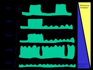
Summary of Classification and Characteristics of Mapleson Circuits Clinical Anesthesiology,Morgan,4th ed.
Summary of Classification and characteristics of Mapsleson Circuits Clinical Anesthesiology,Morgan 4th ed.
Circle System • This is a unidirectional breathing system with CO2 absorption . • Consists of the following- • Inspiratory Unidirectional valves • Inspiratory limb • Expiratory limb • Expiratory Unidirectional valve • Expiratory pop-off valve • Reservoir Bag,CO2 absorber • Fresh Gas in flow • Invented by Brian Sword-1936
Circle System • The circle absorber may be used as a closed or semi-closed system • Closed System:The APL is closed so that no gas escapes from the system.Oxygen flows into the system to replace that consumed by the patient and exhaled CO2 is absorbed by the soda lime • Semi-closed: The APL is opened ,allowing excess gas to escape from the system.This allows higher fresh gas flow rates to be used
Operational requirements of the circle system • The volume of the breathing bag must be greater than the patient’s inspiratory capacity,this is usually estimated at 30ml/kg • Since Soda lime contains 50-70% air around the granules,the volume of the absorber canister should be at least double that of the tidal volume of the patient for optimal efficiency
Fresh Gas flow requirements • In truly closed systems,the patient consumes O2 and expires CO2,which is removed by the absorber.The volume of O2 flowing into the system therefore must equal the patient’s O2 consumption • Resting O2 consumption is approximated by : O2 consumption(ml/min)=10×BW0.75 • The use of Nitrous in closed system presents a problem in that after equlibration nitrous will accumulate in the circuit and can result in a hypoxic mixture,so it is mandatory to have an inspired Oxygen concentration monitor
Avoiding rebreathing in a circle system • The unidirectional valve must be located between the patient and the reservoir bag on both the inspiratory and the expiratory limb • The fresh gas inflow cannot enter the circuit between the expiratory valve and the patient • The APL valve cannot be located between the patient and the inspiratory valve
Dead space in Circle system • The part of tidal volume not involved in alveolar ventilation is termed dead space • Thus an increase in dead space must be accompanied by increase in tidal volume if alveolar ventilation is to remain unchanged • Because of unidirectional valve apparatus dead space is limited to the area distal to the point of inspiratory and expiratory gas mixing at the Y-piece • Unlike Mapleson circuits,the breathing tube length does not affect dead space,but like Mapleson circuits length does affect the circuit compliance
CO2 Absorbers • Base Neutralizing an acid • Acid-Carbonic Acid(H2O +CO2→H2CO3) • The base is the Hydroxide of an alkali or alkaline earth(NaOH-Sodalime,Ba(OH)2-Baralyme) • The end products are Heat of Neutralization, H2O and a carbonate • There are 2 main types of Absorbers commonly used-Soda lime and Baralyme • Newer Absorber-Amsorb consist of Ca(OH)2 andCaCl2,more inert and less degradation of anesthetics
Comparison of Soda Lime and Barium Hydroxide Clinical Anesthsiology,Morgan,4th ed.
Economy of the anesthetic consumption Warming and humidification of the inspired gases because of rebreathing Reduced atmospheric pollution Low fresh gas flow requirements Bulkier than the Mapleson circuit,less portable Because of the many connections there is an increased chance for leaks and disconnections Unidirectional valves can get sticky because of condensation leading to enormous dead space Formation of Compound A with servoflurane Increase in resistance during spontaneous ventitlation Risk of bacterial contamination Advantages Disdavantages
References • Essentials of Anesthetic Equiments,2nd ed. Baha Al-Shaikh,Simon Stacey • Understanding Anesthesia Equipments,4th ed.Jerry A.Dorsch,Susan E. Dorsch • Anesthesia Breathing System,An in-depth review,M Ravishankar • Clinical Anesthesilology,3rd ed G.Edward Morgan,Maged S. Mikhail,Michael J.Murray with C.Philip Larson Jr. • Millers Anesthesia 6th ed,Ronald D.Miller,Robert K.Stoelting • World Federation of Societies of Anesthesiology,Issue7(1997), Article 4,Anesthetic Breathing Systems