Download
1 / 21
210 likes | 237 Views
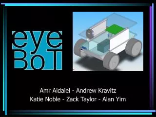
The EyeBot is a remotely operated rover designed for surveillance and monitoring purposes. It features wireless real-time video transmission, temperature sensor, manual operation via computer interface, and more. The rover assembly includes two independent drive-trains, wireless camera, LEDs, and temperature sensor. The power distribution system includes various components for efficient power management and cooling. Users can control the rover using a computer interface, with wireless communication capabilities. The project involves a division of tasks among team members and includes a time schedule and cost estimation.

E N D
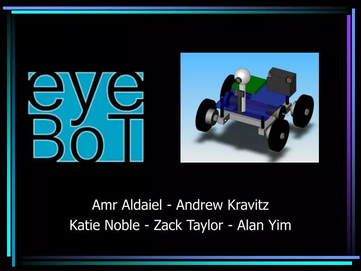
Amr Aldaiel - Andrew Kravitz Katie Noble - Zack Taylor - Alan Yim
Overview • Objectives and features • Block diagram • Microcontroller and FPGA • Rover assembly and mechanics • Peripherals • Power distribution system • User interface and communication link • Risks and contingency plan • Division of tasks • Time schedule • Cost estimation
Purpose • Remotely operated rover to be used for purposes including: • Home/Business surveillance • Hazardous environment monitoring • Accessing low-light and small space environments • Non-intrusive monitoring of disabled and elderly
Features • Wireless real-time video with illumination capabilities • Remote manual operation via computer-based user interface • Temperature sensor • LCD display and keypad Preliminary Goals • Wireless network control • Automatic patrol mode • Smoke detector, CO detector Potential Add-ons
Microcontroller • PIC18F6527 Microcontroller (64 Pin) • Contains 5 on Board PWM • 2 PWM to control vehicle movement • 1 PWM to control camera servo for vertical aim • Onboard EEPROM, RAM and EnhFl memory • Internal Oscillator to sample wheel position • Max Operating Frequency 40MHz • Upward scalable for additional features
FPGA or CPLD • Xilinx XCS10 FPGA • Uses • On Board Control Pad • On Board LCD display • LED information lights for debugging • On Board Switches and Buttons for debugging
Rover Assembly and Mechanics • Two independent drive-trains • Each drive-train driven by a different DC motor • Options • Treads • Left/Right side wheels linked by belts • Front/Back wheels on axles • Optical encoder feedback for automated movement (optional)
Peripherals • Wireless camera • High-intensity illumination LEDs • Temperature sensor • LCD display and keypad Preliminary Goals • Night vision camera capabilities • Smoke detector • Carbon Monoxide detector Potential Add-ons
Power Distribution System Tasks: • Design and build a Power Management Unit (PMU) • Build switching power converters as needed for different parts of the eyeBOT • Ensure power is adequately distributed and efficiently managed • Ensure switching converters are adequately cooled down by heat-sinks and/or fans
Initial PMU Components • 1st Stage Step-Down Converter • 2nd Stage Step-Up/Down Converters • Motor Controller and Gate Driver • H-bridge Inverter • Servo Controller
Non-inverting buck-boost Converter (Could also use a Flyback Converter): Step-Up/Step-Down DC-to-DC Converter
H-Bridge Converter H-Bridge Converter
User Interface • User will interface with the eyeBOT from a base computer. • User will control movement of wheels and camera • Programmed using Visual C#
Communication Link • Camera will communicate wirelessly directly with the base computer • All other devices will communicate to the base computer through an RS-232 cable • Once working, we will upgrade to wireless communication
Risks & Contingency Plan • Errors on PCB • Wire wrap prototype • Power issues • Can use tethered AC power • Visual interface issues • LCD panel rover control • Wireless interfacing issues • Can use tethered RS-232 interface
Division of Tasks • Amr • Power distribution system, LCD/Keypad • Andrew • Microcontroller, FPGA • Katie • Motors & feedback, peripherals, FPGA • Zack • User interface, communication link • Alan • Rover assembly & mechanics, motors