Download
1 / 58
740 likes | 1.45k Views
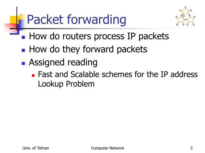
Packet forwarding. How do routers process IP packets How do they forward packets Assigned reading Fast and Scalable schemes for the IP address Lookup Problem. Forwarding vs. Routing. Forwarding : the process of moving packets from input to output The forwarding table Lookup.

E N D
Packet forwarding • How do routers process IP packets • How do they forward packets • Assigned reading • Fast and Scalable schemes for the IP address Lookup Problem Computer Network
Forwarding vs. Routing • Forwarding: the process of moving packets from input to output • The forwarding table Lookup. • How to populate the lookup table? • Routing: process by which the forwarding table is built and maintained • One or more routing protocols • Procedures (algorithms) to convert routing info to forwarding table. Computer Network
Outline • Alternative methods for packet forwarding • IP packet routing • Variable prefix match Computer Network
Techniques for Forwarding Packets • Source routing • Packet carries path • Table of virtual circuits • Connection routed through network to setup state • Packets forwarded using connection state • Table of global addresses (IP) • Routers keep next hop for destination • Packets carry destination address Computer Network
R R R R Datagram Switching • No connection setup phase since it is costly. • Each packet is forwarded independently • Sometimes called connectionless model • Analogy: postal system • Each switch maintains a forwarding (routing) table Packet 2 2 Sender R1 R1 R 4 1 3 1 3 4 4 R 3 2 R2 1 Receiver 3 4 R 3 Computer Network
Router Table Size • One entry for every host on the Internet • 600M entries, doubling every year • One entry for every LAN • Every host on LAN shares prefix • Still too many, doubling every year • One entry for every organization • Every host in organization shares prefix • Requires careful address allocation Computer Network
Outline • Alternative methods for packet forwarding • IP packet routing • Variable prefix match • Routing protocols – distance vector Computer Network
Original IP Route Lookup • Address classes • A: 0 | 7 bit network | 24 bit host (16M each) • B: 10 | 14 bit network | 16 bit host (64K) • C: 110 | 21 bit network | 8 bit host (255) • We need to keep only network address, 221entries. • Address would specify prefix for forwarding table • Simple lookup Computer Network
Original IP Route Lookup – Example • www.cmu.edu address 128.2.11.43 • Class B address – class + network is 128.2 • Lookup 128.2 in forwarding table • Prefix – part of address that really matters for routing • Forwarding table contains • List of class+network entries • A few fixed prefix lengths (8/16/24) • Large tables • 2 Million class C networks Computer Network
CIDR Revisited • Supernets • Assign adjacent net addresses to same org • Classless routing (CIDR) • How does this help routing table? • Combine routing table entries whenever all nodes with same prefix share same hop Computer Network
CIDR Illustration Provider is given 201.10.0.0/21 Provider 201.10.0.0/22 201.10.4.0/24 201.10.5.0/24 201.10.6.0/23 Computer Network
142.12/19 Classless AddressingCIDR A B C D Class-based: 0 232-1 • Class A cover a large range of addresses Classless: 128.9.0.0 65/8 128.9/16 0 232-1 216 128.9.16.14 • Take part of address space for host addresses. Computer Network
128.9.19/24 128.9.25/24 128.9.16/20 128.9.176/20 Most specific route = “longest matching prefix” Classless AddressingCIDR 128.9/16 0 232-1 128.9.16.14 Computer Network
IP Lookup • Packets are forwarded to their destination based on their destination addresses. • Router must find the address of the next hop for each packet by finding the longest prefix matching with the packet destination address. Computer Network
Forwarding Algorithm If the datagram destination address is in the local network deliver packet over the interface else if the network address is in the forwarding table deliver packet to the corresponding next hop else deliver packet to the default router. • For Class address there is exact matching • For Classless address it is prefix matching. Computer Network
Forwarding Table 128.17.20.1 e.g. 128.9.16.14 => Port 2 R2 Prefix Next-hop Port 3 65/8 128.17.16.1 R1 R3 1 4 128.9/16 128.17.14.1 2 2 128.9.16/20 128.17.14.1 3 7 128.9.19/24 128.17.10.1 128.9.25/24 128.17.14.1 2 R4 128.9.176/20 128.17.20.1 1 142.12/19 128.17.16.1 3 128.17.16.1 • It is prefix matching in the table. Computer Network
Requires Routing Table Default Routing Default Routing Default Routing R1 R2 R3 R4 R5 Computer Network
Inside a Router 3. 1. Output Scheduling 2. Forwarding Table Interconnect Forwarding Decision Forwarding Table Forwarding Decision Forwarding Table Forwarding Decision Computer Network
Forwarding in an IP Router • A higher level view from router perspective. • Lookup packet DA in forwarding table. • If known, forward to correct port. • If unknown, drop packet. • Decrement TTL, update header Checksum. • Forward packet to outgoing interface. • Transmit packet onto link. Computer Network
Outline • Alternative methods for packet forwarding • IP packet routing • Variable prefix match Computer Network
IP lookup • Example: If the a packet destination address is 101100111, the next hop will be 8 since 10110011 is the longest matching prefix. Computer Network
Trie Based Methods • Trie or radix tree is a data structure in which each data element is represented by the path to the leaf and no. of internal nodes are the no. of alphabet. • Two branching. • Black node in the leaves represent next hops Computer Network
Trie Based Methods (cont) Trie has been the base of many methods. There are two main problems with trie: • The blank nodes do not correspond to any data element in the lookup table. • The number of branching is small, 2. Both of these add to the height of trie, waste memory and prolong the search time. The Max search time is proportional to string length or O(32) for IPv4 and O(128) for IPv6. Computer Network
Trie Based Methods (cont) Solutions: • Remove or reduce blank nodes, Patricia tree, Path compression method, etc. • Compare 2 or more bits at each steps, Level compression and other methods. • Use tree or other well known data structures. • Other consideration: memory speed is a bottleneck!, minimize memory access. Computer Network
Tree Based Lookup • Comparing prefixes. • Sorting prefixes • Binary prefix Tree. • M_way prefix tree. Computer Network
Sorting prefixes • Question? Why well-known tree structures cannot be applied to the longest prefix matching problem? • Answer- No a well-known method for sorting. • Definition: Assume Aa1a2…an and B=b1b2…bm to be prefixes of (0,1) and • 1.If n=m, the numerical values of A and B are compared. • 2.If n m (assume n<m), the two substrings a1a2…an and b1b2…bn are compared. If a1a2…an and b1b2…bn are equal, then, the (n+1)th character of string B is checked. It is considered B>A if bn+1 is before 1 and B A otherwise. Computer Network
Sorting prefixes (cont) Example- • Sorting is a function to determine the position of each prefix. • Prefixes of table is sorted as: 00010*,0001*,001100*,01001100*,0100110*,01011,001*,01011*,01*,10*,10110001*,1011001*,10110011*,1011010*,1011*,110* Computer Network
Binary prefix tree • Unfortunately, it fails for 101100001000 Why? • Prefixes are ranges and not just a data point in the search space. Computer Network
Binary prefix tree(cont) • Definition: prefixes A and B are disjoint if none of them is a prefix of other. • Definition : prefix A is called enclosure if there exists at least one element in the set such that A is a prefix of that element. • We modify the sort structure; • Each enclosure has a bag to put its data element on it. • Sort remaining elements. • Distribute the bag elements to the right and left according the sort definition. • Apply algorithm recursively. Computer Network
Binary prefix tree (cont) • Example- Prefixes in table 1. First step. The second step, Note-enclosures are in the higher level than the contained elements. (important!) Computer Network
Binary prefix tree (cont) • The final tree structure Computer Network
M_way prefix tree • Problems with the binary prefix tree. • Two way branching. • The structure is not dynamic and insertion may cause problems!. • Divide by m after sorting the strings • Static m_way tree. • Build a dynamic data structure like B-tree. • How to guarantee enclosure to be in the higher level than its contained elements. • Define node splitting and insertion. Computer Network
M_way prefix tree (Cont) • Node splitting: Finding the split point. • Take the median if the data elements are disjoint. • If thereis an enclosure containing other elements, take it as split point. • Otherwise, take an element which gives the best splitting result. • Note, this does not guarantee the final tree will be balanced. Computer Network
M_way prefix tree (Cont) • Insertion: • If the new element is not an enclosure of others, find its place and insert in the corresponding leaf, like B-tree. • Otherwise, replace the closet element with element and reinsert the replace elements. • Resort the resulted subtree, (space division) if necessary. • Building tree is similar to building B-tree. Computer Network
Prefix Abbrv. Prefix Abbrv. 10 - 1101110010 K 01 - 10001101 L 110 - 11101101 M 1011 - 01010110 N 0001 - 00100101 O 01011 - 100110100 P 00010 - 101011011 Q 001100 A 11101110 R 1011001 B 10110111 S 1011010 C 011010 T 0100110 D 011011 U 01001100 E 011101 V 10110011 F 0110010 W 10110001 G 101101000 X 01011001 H 101101110 Y 001011 I 00011101 Z 00111010 J 011110110 II M-way prefix tree (cont) • Example Computer Network
M-way prefix tree (cont) • We insert prefixes randomly. • The tree uses 5 branching factor (at most 4 prefixes in each node) • Insert 01011, 1011010, 10110001 and 0100110. Then, adding 110 cause overflow. Split node 10110001 (0100110,01011) (1011010, 110) (all element are disjoint) Computer Network
M-way prefix tree (cont) • Insert 10110011, 1101110010, 00010. Adding 1011001 causes overflow. 10110001 1011010 (00010,0100110,01011) (1011001,10110011) (110,1101110010) (case 3 of splitting) • Latter adding 1011 cause problem. It is the case of adding an enclosure. We will have space division. Computer Network
M-way prefix tree (cont) • The final tree • The tree supersede B-tree or B-tree is a special case of this tree. Then, when data element are relatively disjoint, the height of tree is logMN. Computer Network
DMP-Tree Max. height No. of Data • BF is Branching factor in the internal nodes. • No. of Data is in1000s. Computer Network
DMP-Tree No. of Data • Number of prefixes in the right. Computer Network
DMP-Tree • Height of tree for 100K data prefixes. Height Branching Computer Network
Implementation: Tree Nodes Internal nodes Branching factor • Internal nodes. • Each prefix has a left and right pointer which are pointing to left and right subtrees respectively. • We can have N prefixes in each internal node. Then, N+1 is the branching factor. • The bigger N, the faster search time, but the more logic is needed. • Port is the address of the port in the switch to which the packet will be sent. Leaf nodes Computer Network
Tree Nodes • Leaf nodes. • There is no left and right subtree pointers. • The number of prefixes in the leaf node is M. • The leaf nodes are stored in a off chip memory to make the scheme scalable to the large number of prefixes. Computer Network
Branching Factor • What is the best number for N? (Branching factor) • The bigger N, the faster search process. (Fact 1) • The bigger N, the more memory pins are and usually the more mem. Bandwidth is needed (Fact 2). • The bigger N, the more logic we need to process the node (Fact 3). • Simulation result shows • The bigger N, the better memory utilization in the memory. • For N 8, the max. height of the tree does not decrease considerably. Computer Network
Simulation result • Total memory: assuming one memory block and OC-192. Computer Network
Branching Factor • It seems any number between 8-16 is reasonable. But, N=9 gives a better search time, memory size. • Assuming 9 branching factors in the internal node, %50 node utilization and 128K prefixes, we need max. 128K/4.5= 28.5K address. Then, 15 bitaddress for left and right pointers are more than enough. But, we need more for off chip addressing Computer Network
Branching Factor • In order to make the internal node branching and leaf node branching even, M=10. • If we want to read a node at once, we will need 41x10=410 pins which is difficult to support in one chip. • We can divide a node in two and read/write in two clock cycles. This reduce the memory pins to 205 which is affordable. Computer Network
Memory requirement • Prefix tree: Assuming 128K prefixes. N = 9 (BF) and M=10 (BF in leaves), the majority of prefixes, %80 will be in leaves, assume %65 node utilization, # of ave prefixes in a leaf node node = 10*0.6 5= 6.5 # of leaf nodes 128Kx%80x2/6.5 = 31.5K and %10 overhead 35 K Total off chip memory = 35K x 205(Mem BW) = 7.2 Mbits Then, we need 16 bits for addressing. 1 bitfor internal/external. # of internal nodes= 128Kx%20/5.8=4.41K and %10 overhead 4.9 K Total on chip memory=4.9Kx529K 2.6Mbits • Port to link address mapping table. For each port corresponding link address Max. 256 ports, on chip, some mem for indexing Computer Network
Memory requirement • In summary: • Note: • Branching factor is the # of branching in internal nodes. • The size of the memory scales with the size of data or # of prefixes. • Power dissip. depends on the r/w freq, current & core voltage • Considering Faraday Mem. Modules A 10Kx32 bits single port mem size is 36x1.45 mm2. Computer Network
Port2Addr MEM Ctrl Overall Design Memory Mem. Ctrl root addr Update Search Search To/From NP root content Insertion update delete CPU Inter face To/From CPU Output mem Ctrl To/From out Mem Computer Network