Download
1 / 7
80 likes | 258 Views
Basic Anatomy of a Sensor System. Signal Conditioning. Microprocessor. Sensor. A/D. Analog Mux. A/D. Sensor. H/L. Sensor. Control Bus. 8 bit Analog to Digital Converters Share A/D via analog multiplexer Analog signal conditioning. Sensing Challenges. Switch.

E N D
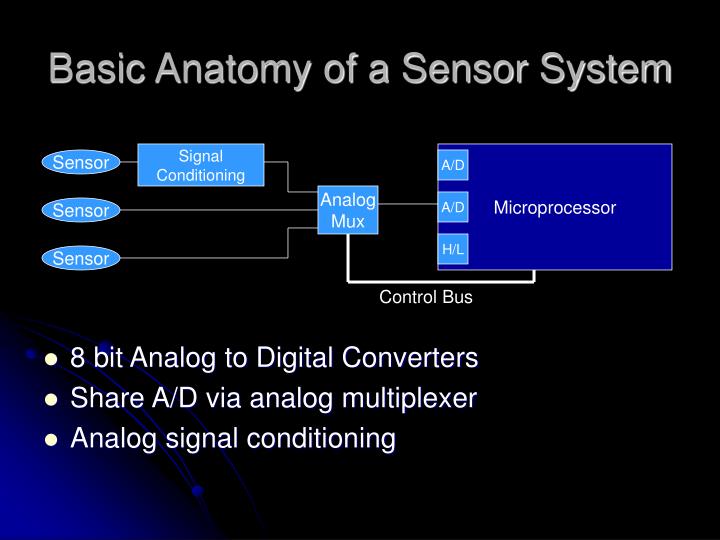
Basic Anatomy of a Sensor System Signal Conditioning Microprocessor Sensor A/D Analog Mux A/D Sensor H/L Sensor Control Bus • 8 bit Analog to Digital Converters • Share A/D via analog multiplexer • Analog signal conditioning
Switch • As easy as on / off, right? ...nope signal bounces
Temperature • MTS102 (available in parts shop) • Linear temp response • Use Diff Amp with V2 = 0.637mV, V1 = buffered MTS102 output, R1=1k, R2=40k
Infrared • Modulate infrared LED at 40kHz • LM555 Timer / LC circuit • Columnate LED with Bic Pen • Hack Sharp GP1U58X to obtain analog output reading (may be obsolete) • (http://www.mil.ufl.edu/imdl/handouts/sharphack.pdf) LED 40kHz Modulation Bic Sharp IR Sensor 1.5V to 2.5V output 100ms Rise time
Obtaining Datasheets • Manufacturers Home Pages • Data Bookshelf (http://www.crhc.uiuc.edu/~dburke/databookshelf.html) • Links to Manufacturer’s homepages and other resources • Datasheet Repositories • www.questlink.com • www.tds-net.com • www.info-quick.com