Download
1 / 16
190 likes | 361 Views
Vision processing for robot navigation. Autonomous robot vacuum cleaner. Introduction. Explain the image processing used for robot navigation of Sir-Sux-Alot Image processing overview Attempted Solution Final Solution. Problem and solution.

E N D
Vision processing for robot navigation Autonomous robot vacuum cleaner Nicholas Frank, nicholasfrnk@yahoo.com
Introduction • Explain the image processing used for robot navigation of Sir-Sux-Alot • Image processing overview • Attempted Solution • Final Solution Nicholas Frank, nicholasfrnk@yahoo.com
Problem and solution • The original problem is to pickup the most rice in the least amount of time. • The arena is a simulate room with obstacles. • The best solution is to navigate in a systematic route around the simulated room. Nicholas Frank, nicholasfrnk@yahoo.com
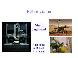
Architecture • A camera above the vacuum arena will identify the location and barring of the robot. • The location and barring are transmitted via UDP to the java navigation engine which tells the robot where to go via serial RF. Nicholas Frank, nicholasfrnk@yahoo.com
Vision Requirements • The goal of this vision system is to find the location and bearing of the robot. • Robustness. This vision system must be able to work in unknown light conditions. Nicholas Frank, nicholasfrnk@yahoo.com
Minimum Data Required • Only two points are necessary. • Identify each point. Connect the points to get the bearing. • Find the mid-point to get center. • Knowing the distance between the points and the relationship to the corners you can calculate the outer dimensions of the robot. Nicholas Frank, nicholasfrnk@yahoo.com
Image • Each pixel is represented using three components (red,green and blue): Alpha=a(x,y); Red=r(x,y); Green=g(x,y);Blue=b(x,y); • Each pixel is a 32-bit number • Each color is 8-bit having a value between 0-255. • F=f(x,y)=(a(x,y),r(x,y),g(x,y),b(x,y)) • The image is represented as a 2-D array [F1,F2,..Fn] • Color representation: Nicholas Frank, nicholasfrnk@yahoo.com
Failed Solution • 2 Ultra bright LEDs: green & red • Background subtraction • Hypothesis: • Using background subtraction everything but the robot should be black. • The LEDs will have a black back ground so only the LEDs should be seen. • The centroid of each LED will be found. • Then the predominate color of each centroid will be found: red or green. Nicholas Frank, nicholasfrnk@yahoo.com
Background subtraction • Capture the first image I1 then subtract it from I2 displaying only the pixels where there is a difference. Then use I2 and subtract it from I3. The general form is In – I(n+1) • Problem 1 (variable pixel colors) : • Pixels of an image change colors when nothing changes. • Solution 1a: Take the max or min of the background image pixels then subtract from the average image. • Solution 1a produces it own problems. Any change in the camera position or lighting will invalidate the background causing most of the image to be displayed. (Demo background subtraction) • Problem 2 (Halo effect) : • The change in the image is such a distortion of the surrounding pixels that the image gets a halo around the change. Nicholas Frank, nicholasfrnk@yahoo.com
Chosen Solution • Find object with 3 dots • Original web cam image • Blend image into background using web cam settings. • Using a color histogram threshold the image to Black and white • Use a recursive flood fill algorithm to find blobs. The north,south,west and east values of the blobs. Then count the holes in the blobs. The robot will only have 3 holes. • Once the holes are identified it is possible to use there relationship to each other to figure out barring. Nicholas Frank, nicholasfrnk@yahoo.com
Color Histogram • As mention earlier each pixel’s color is represented by an 8-bit value of red, green and blue. That value is between 0 and 255. • The color histograms graph represents: • Y axis: the number of times a color is used. • X axis: the color represented. • The graphs are: • All color representations combined • Red,green and blue only Nicholas Frank, nicholasfrnk@yahoo.com
Threshold with Color Histogram • The color histogram is used as a threshold to map the image to black and white. • You may have already noticed two distinct humps in the graph. • The left hump and bigger hump is the background • The right hump is everything more rich in color then the background • The threshold bars set between the two humps produce the image to the right • A dynamic threshold looks for the end of the first hump. This made the vision system resistant to changing light conditions such as flash photography. Nicholas Frank, nicholasfrnk@yahoo.com
Flood Fill • What is Flood Fill? • Technique to fill the closed area with an interior color to be replaced by fill color. Nicholas Frank, nicholasfrnk@yahoo.com
Flood Fill Algorithm • Fast recursive flood-fill Algorithm • public void fillFast(int x, int y, int fill) { if ((x < 0) || (x >= raster.width)) return; if ((y < 0) || (y >= raster.height)) return; int old = raster.getPixel(x, y); if (old == fill) return; raster.setPixel(fill, x, y); fillEast(x+1, y, fill, old); fillSouth(x, y+1, fill, old); fillWest(x-1, y, fill, old); fillNorth(x, y-1, fill, old); } • private void fillEast(int x, int y, int fill, int old) { // now it only checks for one direction. if (x >= raster.width) return; if (raster.getPixel(x, y) == old) { raster.setPixel(fill, x, y); // only three direction of recursion. fillEast(x+1, y, fill, old); fillSouth(x, y+1, fill, old); fillNorth(x, y-1, fill, old); } } Nicholas Frank, nicholasfrnk@yahoo.com
How flood fill was used • Once a blob was found it got flood filled. • The most north,south,west and east points were recorded during the flood fill. These points are represented with the white dots. • The max points were used to calculate the center which is represented by a white dot. • The blob was next scanned for holes which were then flood filled to calculate there center points. • If a blob had three holes it was identified as the robot. • All other blobs were ignored. Nicholas Frank, nicholasfrnk@yahoo.com
Acknowledgements • Flood-Fill Algorithm, By Junichi Edamitsu • http://research.microsoft.com/vision/ • http://research.microsoft.com/projects/VisSDK/ • P.F. Whelan and D. Molloy (2000), Machine Vision Algorithms in Java: Techniques and Implementation, Springer (London), 298 Pages. ISBN 1-85233-218-2. Nicholas Frank, nicholasfrnk@yahoo.com