Download
1 / 25
300 likes | 346 Views
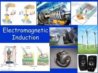
Dive into Michael Faraday’s groundbreaking experiment on electromagnetic induction, magnetic flux, and Faraday’s law. Discover how generators work and the principles of AC versus DC generators.

E N D
Michael Faraday • 1791 – 1867 • Great experimental scientist • Invented electric motor, generator and transformers • Discovered electromagnetic induction • Discovered laws of electrolysis
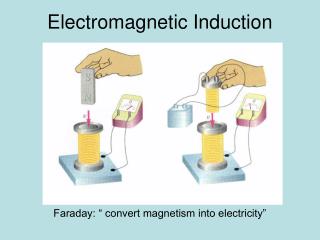
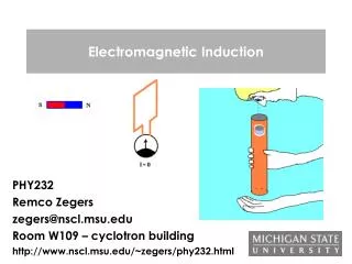
Faraday’s Experiment – Set Up • A current can be produced by a changing magnetic field • First shown in an experiment by Michael Faraday • A primary coil is connected to a battery • A secondary coil is connected to an ammeter
Faraday’s Experiment • The purpose of the secondary circuit is to detect current that might be produced by the magnetic field • When the switch is closed, the ammeter reads a current and then returns to zero • When the switch is opened, the ammeter reads a current in the opposite direction and then returns to zero • When there is a steady current in the primary circuit, the ammeter reads zero
Faraday’s Conclusions • An electrical current is produced by a changing magnetic field • The secondary circuit acts as if a source of emf were connected to it for a short time • It is customary to say that an induced emf is produced in the secondary circuit by the changing magnetic field
Magnetic Flux • The emf is actually induced by a change in the quantity called the magnetic flux rather than simply by a change in the magnetic field • Magnetic flux is defined in a manner similar to that of electrical flux • Magnetic flux is proportional to both the strength of the magnetic field passing through the plane of a loop of wire and the area of the loop
Magnetic Flux • When the field is perpendicular to the plane of the loop, as in a, θ = 0 and ΦB = ΦB, max = BA • When the field is parallel to the plane of the loop, as in b, θ = 90° and ΦB = 0 • The flux can be negative, for example if θ = 180° • SI units of flux are T. m² = Wb (Weber)
Magnetic Flux, final • The flux can be visualized with respect to magnetic field lines • The value of the magnetic flux is proportional to the total number of lines passing through the loop • When the area is perpendicular to the lines, the maximum number of lines pass through the area and the flux is a maximum • When the area is parallel to the lines, no lines pass through the area and the flux is 0
Electromagnetic Induction –An Experiment • When a magnet moves toward a loop of wire, the ammeter shows the presence of a current (a) • When the magnet is held stationary, there is no current (b) • When the magnet moves away from the loop, the ammeter shows a current in the opposite direction (c) • If the loop is moved instead of the magnet, a current is also detected
Electromagnetic Induction – Results of the Experiment • A current is set up in the circuit as long as there is relative motion between the magnet and the loop • The same experimental results are found whether the loop moves or the magnet moves • The current is called an induced current because is it produced by an induced emf
Faraday’s Law and Electromagnetic Induction • The instantaneous emf induced in a circuit equals the time rate of change of magnetic flux through the circuit • If a circuit contains N tightly wound loops and the flux changes by ΔΦB during a time interval Δt, the average emf induced is given by Faraday’s Law:
Motional emf • A straight conductor of length ℓ moves perpendicularly with constant velocity through a uniform field • The electrons in the conductor experience a magnetic force • F = q v B • The electrons tend to move to the lower end of the conductor
Motional emf • As the negative charges accumulate at the base, a net positive charge exists at the upper end of the conductor • As a result of this charge separation, an electric field is produced in the conductor • The potential difference between the ends of the conductor can be found by • ΔV = B ℓ v • The upper end is at a higher potential than the lower end
Generators • Alternating Current (AC) generator • Converts mechanical energy to electrical energy • Consists of a wire loop rotated by some external means • There are a variety of sources that can supply the energy to rotate the loop • These may include falling water, heat by burning coal to produce steam
AC Generators, cont • Basic operation of the generator • As the loop rotates, the magnetic flux through it changes with time • This induces an emf and a current in the external circuit • The ends of the loop are connected to slip rings that rotate with the loop • Connections to the external circuit are made by stationary brushes in contact with the slip rings
AC Generators, final • If the loop rotates with a constant angular speed, ω, and N turns ε = N B A ω
DC Generators • Components are essentially the same as that of an ac generator • The major difference is the contacts to the rotating loop are made by a split ring, or commutator
DC Generators, cont • The output voltage always has the same polarity • The current is a pulsing current • To produce a steady current, many loops and commutators around the axis of rotation are used • The multiple outputs are superimposed and the output is almost free of fluctuations
Motors • Motors are devices that convert electrical energy into mechanical energy • A motor is a generator run in reverse • A motor can perform useful mechanical work when a shaft connected to its rotating coil is attached to some external device
Nikola Tesla • 1865 – 1943 • Inventor • Key figure in development of • AC electricity • High-voltage transformers • Transport of electrical power via AC transmission lines • Beat Edison’s idea of DC transmission lines
Transformers and Transmission of Power A transformer consists of two coils, either interwoven or linked by an iron core. A changing emf in one induces an emf in the other. The ratio of the emfs is equal to the ratio of the number of turns in each coil:
Transformers and Transmission of Power This is a step-up transformer – the emf in the secondary coil is larger than the emf in the primary:
Transformers and Transmission of Power Energy must be conserved; therefore, in the absence of losses, the ratio of the currents must be the inverse of the ratio of turns:
Electrical Power Transmission • When transmitting electric power over long distances, it is most economical to use high voltage and low current • Minimizes I2R power losses • In practice, voltage is stepped up to about 230 000 V at the generating station and stepped down to 20 000 V at the distribution station and finally to 120 V at the customer’s utility pole
Transformers and Transmission of Power Transformers work only if the current is changing; this is one reason why electricity is transmitted as ac.