Download
1 / 42
480 likes | 796 Views
COMPUTER NETWORKS. NETWORK TOPOLOGY. Network Topology: refers to the spatial organization of network devices, the physical routing of network cabling, and the flow of messages from one network node to another. Network Topology can refer to physical and logical.

E N D
NETWORK TOPOLOGY Network Topology: refers to the spatial organization of network devices, the physical routing of network cabling, and the flow of messages from one network node to another.
Network Topology can refer to physical and logical. Physical topology refers to the physical placement of cables and device connections to those cables Logical topology refers to the path that messages travel from node to node.
There are three common types of network topology: StarBusRing
Star Topology: use a central node to which all other nodes are connected. A central node is a transfer point.
Advantage of the star topology is relatively simple wiring connect to the hub. Primary disadvantage of star topology is the failure of the hub disables the entire network.
Bus topology connects each node to a common transmission line. And at the end of the bus there is a terminating resistor to absorb signals and prevent them from bouncing back down to the common transmission line.
Primary advantage of the bus topology is relatively simply wiring and low susceptibility to failure. • There is no central node that can fail and disable the entire network. • The fail of any node does not prevent other nodes from transmitting and receiving messages.
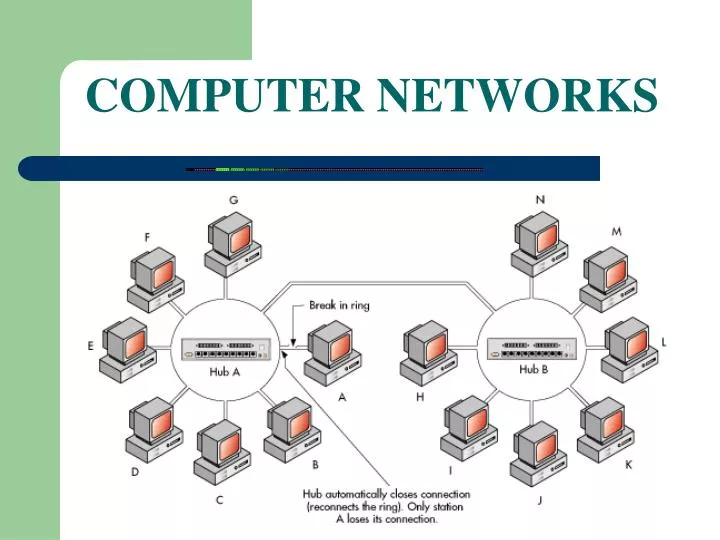
Ring Topology: connects each node to two other nodes and the entire network forms a closed loop. Message is passed around in one direction.
The primary advantage of ring topology are long maximum network length and low susceptibility to noise and distortion. The disadvantage of ring topology are susceptibility to failure and difficulty in adding, deleting, or moving nodes
LAN (Local Area Network): is a network covering a floor or building.
WAN (Wide Area Network): is the entire campus network. LANs are interconnected to form WAN
Each time the node want to send a message. It sends a message announcing its presence and its address to the nearest hub. Each hub maintains the table of address and transmission lines or connection ports and uses that table to make routing decision.Example How message is passed in Local Area Network Routing
WAN using router to routes the message. Each router knows address and physical location of its own nodes and knows other nearby routers and the group of addresses that they control.Example Wide Area Network Routing.
There are 2 categories to avoid collision:CSMA/CDToken passing. Media Access Control Media Access Control (MAC) protocol specifies rules for accessing a shared transmission medium or to avoid Collision.
CSMA/CD Carrier sensed- each device that wants to send data along the share media “listen” to the media to detect if it is in use by other users. Multiple access – any device can transmit if it detect that media is clear. Collision detection – each device monitors its data in case it collides with other data. A collision can occur if two devices listen to the media, decide it is clear and then transmit at the same time.
Token passing • Token passing message is passed from node to node and only the node that “possesses” the token is allowed to transmit messages.
NETWORK HARDWARE • Network interface units or Network interface card. • Hub. • Bridges • Routers • Switches.
Network Interface Unit (NIU): is a device that connects a network node such as computer, printer to a network transmission cable.
Hub: is used to connect nodes in a LAN. And the transmission lines are connected to an NIU with standard connecter RJ45.
Bridge (or repeater): is the device that connects two networks and forwards packets between them.
Router: is intelligent bridge that can connect to more than two networks and exchange information to improve routing decisions.
Switch: functions similar to a bridge and hub but it has more input connections for computers and other network nodes. A switch determines which computer is intended destination and pass message to that only computer.
OSI: is the international standard that divides network architecture into seven layers and each layer uses the service of layer below. OSI NETWORK LAYERS APPLICATION PRESENTATION SESSION TRANSPORTATION NETWORK DATA LINK PHYSICAL
TCP/IP • TCP/IP (Transmission Control Protocol and Internet Protocol) is a set if protocols designed for supporting global internetworking.
TCP: is a connection-oriented protocol provides the framework to check for lost messages by establishing a connection with an intended recipient before transmitting messages. • IP accepts packets called datagrams from TCP and other higher session layer protocols. IP translates datagrams into a format suitable for transport by the physical network.
IP: is also called connectionless protocol. Because IP sends a datagram to the appreciate gateway and assumes that the datagram will find its way successfully to the intended recipient .. TCP is a connection-oriented protocol. It provides the required framework to check for list messages by establishing a connection with an intended recipient before transmitting messages.
TCP connections are established through a port and socket. • Port: is a TCP connection with a unique integer number. • Socket: is the combination of an IP address and a port number
NETWORK STANDARDS The Institute of Electrical and Electronic Engineers (IEEE) has drafted a number of telecommunication and network standards, referred to as the IEEE 802 standards.
Application layer: is a program such as Web browser, email client respond to high-level requests for network services. Back
Presentation Layer: ensures that data transmitted by one network node is correctly interpreted by other network node. Back
Session Layer: establishes and manages communication sessions. Back
Transport Layer: divides messages into packets suitable for transmission over the network and adding a sequence number to each packet. Back
Network Layer: routes the packets to the proper destination. It will rout to the nearest LAN hub or router. Back
Data Link Layer: is the interface between network software and hardware. It manage packet transfer from secondary or primary to NIU. Back
Physical Layer: is the layer at which communication between device actually take place. Back