Download
1 / 40
400 likes | 441 Views
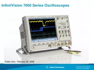
HP 54600B. Digital Oscilloscope. Oscilloscopes. Alex Jones COE 0501. Protect Yourself:. Avoid contact with Voltage or Current Sources. •. Use shrouded test leads and alligator clips. •. Leads:. Connect to oscilloscope first;. Connect/disconnect at source so loose lead is dead. •.

E N D
HP 54600B Digital Oscilloscope Oscilloscopes Alex Jones COE 0501
Protect Yourself: Avoid contact with Voltage or Current Sources • Use shrouded test leads and alligator clips. • Leads: Connect to oscilloscope first; Connect/disconnect at source so loose lead is dead. • Connect probe to ground before connecting to high. Protect the Scope: • 400V maximum on input. • Use probes to reduce high voltages. • Be familiar with user’s guide. Safety Tips
Oscilloscopes • Oscilloscopes display the relationship of Voltage vs. Timewaveformsfor analog and digital signals. • The display is like a dynamic plot. Therefore we must be able to adjust the scales and offsets of the “plot” of the waveform. • Voltage - set the Input / vertical scale factor • Time- set the horizontal / time scale factor • Position (Vertical and Horizontal) • Triggering - when should it start to draw? • Storage - keep a copy • Measurement - measure features of the waveform
Save/Recall Autoscale/ Display/Print Triggering Vertical Scale Intensity Ground Inputs External Trigger Calibration Power Front Panel Features Horizontal Position Measurement Cursors Storage Vertical Position Horizontal Scale What’s wrong with this picture?
Task - Front Panel • Draw a picture in your lab notebook of the front panel of your scope. • Every button, knob, and connector should be depicted and labeled. • Use an entire page of your lab notebook for this.
Task - Front Panel • On the next page of your notebook, make a list of the buttons, knobs, and connectors on the front panel. • As you learn about each item in the list, write a brief description of it in your notebook.
• This switch turns the oscilloscope on and off. Power Switch
• This knob adjusts the brightness of the display • If no trace is seen, it may be because the intensity knob is set too low. Intensity Knob
• This connection may be used to ground probes. Ground Connection
• These connections are used to connect coaxial cable, probes, etc. to the oscilloscope. • The outside of the connector is grounded. Signal Inputs
£ • Make sure the input voltage level 400 V. • Connect a BNC cable or a probe to a channel input. • Connect the other end of the cable or probe to the device to be measured. Connecting a Signal
Task - Calibration Signal • Connect a probe to channel 1. • Connect the red lead to the calibration signal below the display. • Push the Auto-scale button. • Draw a picture of the resulting waveform in your lab notebook.
addition menu volts per division volts per division channel menu channel menu position knob position knob Vertical Section
Input Selection • Use the push buttons to enable/disable eachchannel. • These also enable the “soft keys” under the display
D V DC vs. AC Coupling • For digital signals we almost always want DC coupling. • AC coupling centers the signal on 0v • Digital signals swing between 0v and 5v
• Use the vertical volts/div knobs (located above the channel input connector) to scale the signal vertically on the screen. Vertical Scale
Task - Calibration Signal • Adjust the volts/div knob so that the entire calibration waveform is visible on the screen, and appears as large as possible. • Record the volts/div setting in your lab notebook. • Use the scope to measure the amplitude of the calibration waveform.
• Use the vertical position knob (located above the channel input connector) to position the signal vertically on the screen. Vertical Positioning
delay knob main/delayed menu time per division Horizontal Section
• Turn the time/div knob to adjust the sweep speed (time base). • The sweep speed has a range from 2ns to 5s. Time Base
Task - Calibration Signal • Adjust the time/div knob so that one period of the calibration waveform is visible. • Record all time base parameters in your lab notebook. • Use the scope to measure the period of the calibration waveform. • Compute the frequency of the waveform.
• Use the delay knob to move the signal horizontally. • Note the value displayed on the status line. Horizontal Positioning
source menu trigger level knob mode menu slope/coupling menu holdoff knob Trigger Section
• Use this menu to assign a trigger source. • The choices are line, CH1, CH2 and external. Triggering Source Menu
• Use this menu to choose a trigger mode. • The choices are auto level, auto, normal, single, and TV. Triggering Mode Menu
• Use the level knob to set the trigger voltage. • The screen will display the trigger level in inverse video and a horizontal line representing the trigger location. Triggering
1 Delay Triggering level + Slope - Slope Triggering
Custom Features Autoscale Voltage menu Time menu Cursor menu Storage Delay
setup menu time menu voltage menu cursor menu trace menu cursor knob autoscale print/utility display menu Custom features
£ • Sets the Time Scale and Vertical Scale for all inputs Uses the highest active channel (1,2,3,4, ext) as trigger • Auto Scale
• Use this menu to make automatic voltage measurements. made using the softkeys below the display. • Measurements include peak to peak voltage, rms voltage, max voltage, etc. The choice is Voltage Menu
Vp Vrms Vpp time Vrms = 0.707 Vp (Sine wave) Voltage Readings
• Use this menu to measure frequency, period, duty cycle, risetime, etc. Time Menu
Period 1 T Hz f = T w = 2 × p × f rad/s ( t ) time Frequency and Period
• This menu brings up a list of cursor commands and activates the cursor knob. • The cursors can be used to measure specific voltages, times, etc. Cursor Menu
Storage • These buttons control the storage features of the scope. • Run, Stop, Auto-store, Erase • Save, Recall
Storage • Run - Normal operation • Stop - Keep the most recent trace, do not overwrite • Auto-Store - Keep overwriting traces, with dim lines • Erase - Erase all traces • Save/Recall • Trace - Can store 2 “screen dumps.”Brings up soft keys • Settings - Can store scope settings for reuse
Delay • This button enables the use of two time-bases for the same signal • This gives the ability to have a global and zoomed picture of the waveform at the same time. • It enables a soft key menu (XY, Vernier, Time Ref)
Storage • Run - Normal operation • Stop - Keep the most recent trace, do not overwrite • Auto-Store - Keep overwriting traces, with dim lines • Erase - Erase all traces • Save/Recall • Trace - Can store 2 “screen dumps.”Brings up soft keys • Settings - Can store scope settings for reuse