Download
1 / 1
10 likes | 91 Views
The Gamma-ray Large Area Space Telescope:. Pair Conversion Telescopes. Scintillator. Tracker.

E N D
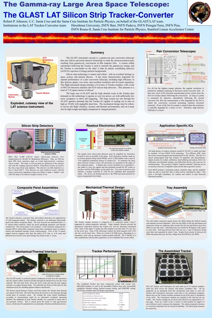
The Gamma-ray Large Area Space Telescope: Pair Conversion Telescopes Scintillator Tracker Left: reconstruction of the conversion of a photon from a CERN test beam. A 470 MeV gamma ray (yellow line) enters a tower and converts in the sixth tungsten foil. The blue lines show the reconstructed trajectories of the electron and positron. Right: schematic depiction of a photon conversion in the Tracker. Conversion point, followed by multiple scattering Multiple scattering here does not hurt much, as long as a point is measured immediately following. Calorimeter For all but the highest energy photons, the angular resolution is limited by multiple scattering in the heavy-metal converter foils. In that case, most of the direction measurement power comes from the first two tracker planes following the conversion. As long as a point is measured by detectors immediately following the second converter foil, then the measurement is only degraded by the foil in which the conversion occurred (assuming minimal structural material). If one of the first two points is missed, then the resolution is typically degraded by a factor of two. Therefore, high detector efficiency is crucial. Application Specific ICs Readout Electronics (MCM) Machined corner radius with bonded flex circuit. Silicon Strip Detectors Flex Circuit Interconnect Readout ICs Detector Calibration mask and capacitors Structural Closeout Wall Gr/CE Face Sheet Control logic Trigger and Data mask registers Bias Resistor Control logic 4-deep event memory Composite Panel Readout IC Readout Controller IC 64 amplifier-discriminator channels. 2 DACs Adhesive bond 37-pin nano-connector with connector saver 8-layer PWB I/O pads and protection structures Amplifier-Discriminator Chip Readout Controller Chip Memory The right-hand quarter of an MCM (multi-chip readout module). The high density of readout channels needed by GLAST is readily provided by standard 0.5-m CMOS VLSI technology. Two different ASIC chips have been custom designed and manufactured for the Tracker. The first is a mixed analog-digital chip that includes 64 amplifiers and discriminators, digital circuitry for control, calibration, data buffering and readout, DACs for calibration and threshold settings, and differential drivers and receivers for communication. The second is a digital “readout controller” chip that acts as an interface between 24 amplifier chips and the data acquisition system. Each MCM includes 2 redundant readout controller chips, and the amplifier chips are able to send their data to either and be controlled by either. This gives a left-right redundancy for readout and control of each front-end electronics module. Thermal Boss The signals from silicon-strip detectors must be amplified by electronics located as close as possible to the strips. Each electronics module, made on an 8-layer printed wiring board (PWB), serves 4 SSD ladders with a total of 1536 amplifiers distributed among 24 readout ICs. To minimize the dead space between Tracker towers, the electronics are mounted on the edges of the composite panels. A Kapton flex circuit is bonded over a machined 1-mm radius to carry the signals and bias potentials around the 90º corner to interface with the SSD ladders on the panel face. Two nano-connectors each interface a readout controller IC with the two redundant data acquisition cables. The 26 ICs are bonded directly to the PWB and interconnected by epoxy-encapsulated wire bonds. Aluminum Honeycomb Core MCM Closeout Wall 6-inch wafer before cutting out the SSD Edge bond and wire bonds between 2 SSDs More than 11,000 8.95-cm square silicon-strip detectors were manufactured for GLAST by Hamamatsu Photonics. They are 400 um thick PIN diode structures made on 6-inch high-resistivity n-intrinsic silicon wafers. 384 strips of 228 m pitch are patterned on the junction side with AC coupling capacitors built in. Polysilicon resistors are used to bias the p-type diode strip implants. The detectors are fully depleted at a bias of about 100 V. Four detectors are edge bonded in series, with the strips connected by aluminum wedge wire bonds, to make a “ladder,” each with 384 strips of an effective length of about 35 cm. Composite Panel Assemblies Tray Assembly SSDs Bias-Circuit Structural Tray Panel The First Completed Flight Tray Converter Foils MCM Bias-Circuit The Tracker detectors, converter foils, and readout electronics are supported by 19 stiff composite panels. The primary structure is an aluminum honeycomb faced with carbon composite sheets. The four closeouts are machined from a 3-D carbon-carbon material, which has good machining properties and thermal conductivity. The lowest panel is an exception—it has closeouts composed of a stronger M55-J carbon-fiber composite faced with a machined veneer of carbon-carbon and machined titanium corner reinforcements. Four of the 19 panels support heavier tungsten foils than the others (0.72 mm vs. 0.10 mm) and therefore have heavier cores and stronger face sheets (6 ply vs. 4 ply). SSDs The stiff carbon composite panels protect the SSDs during the Delta-II launch and maintain accurate alignment. Each tray has SSDs on the top and bottom and electronics along two opposing sides (except that the top and bottom trays have SSDs on one side only). Alternating trays are rotated by 90 degrees with respect to each other. Each gap between trays thus has an x-y pair of detectors facing each other and separated by about 2 mm. Kapton bias circuits lie between the SSDs and panel and carry the bias voltage from the MCMs to the SSDs. Mechanical/Thermal Interface Thermal Straps Cable Termination & Support Nest for Alignment Targets Flexures The GLAST tracker is cooled by passive conduction of heat from the electronics into the carbon-carbon closeout and then through the thermal boss into the tower sidewall. The heat then flows down the tower walls and into the grid support structure via copper thermal straps. The sidewalls are faced on both sides by thin aluminum layers for shielding against radiative interference. The flexure mount between Tracker and Grid isolates the Tracker from thermal movement of the Grid. The bolts that fasten the flexures to the Grid pass through nested pairs of eccentric cones. By rotating the cones before installation, according to measurements made by an automated coordinate measuring machine, the alignment of each Tracker module was corrected to ensure that it sits precisely vertical. This is critical given the small 2.5 mm gap between towers, which must be maintained to accommodate vibration and thermal motion. The GLAST LAT Silicon Strip Tracker-Converter Robert P. Johnson, U.C. Santa Cruz and the Santa Cruz Institute for Particle Physics, on behalf of the GLAST/LAT team. Institutions in the LAT Tracker-Converter team: Hiroshima University, INFN Bari, INFN Padova, INFN Perugia/Terni, INFN Pisa, INFN Roma-II, Santa Cruz Institute for Particle Physics, Stanford Linear Accelerator Center Summary The GLAST instrument concept is a gamma-ray pair conversion telescope that uses silicon microstrip detector technology to track the electron-positron pairs resulting from gamma-ray conversions in thin tungsten foils. A cesium iodide calorimeter following the Tracker is used to measure the gamma-ray energy, and the Tracker is surrounded on the other 5 sides by plastic scintillating detectors (ACD) for rejection of charge-particle backgrounds. Silicon strip technology is mature and robust, with an excellent heritage in space science and particle physics. It has many characteristics important for optimal performance of a pair conversion telescope, including high efficiency in thin detector planes, low noise, and excellent resolution and two-track separation. The flight-instrument design includes a 44 array of Tracker modules, with a total of 884,736 detection channels and 9216 silicon-strip detectors. This amounts to a total of 73.8 square meters of silicon! The large size of GLAST and the high channel count in the Tracker puts demands on the technology to operate at very low power, yet with sufficiently low noise occupancy to allow self triggering. The large cosmic-ray rate through the GLAST aperture demands that the Tracker be capable of reading out at rates as high as 10 kHz with negligible dead time. The mechanical design must be robust, to survive the flight vibration, vacuum, and thermal environments, and yet it must also be light weight and highly transparent to charged particles. ACD Scintillating Tile Grid Tracker Module Calorimeter Module Exploded, cutaway view of the LAT science instrument. Mechanical/Thermal Design Composite Panel Inverted Tower with Sidewall Removed Composite Sidewall Readout Electronics Titanium Flexures Flex-Circuit Cables The Tracker module structure is composed of 19 composite panels (“trays”) supported by carbon-composite sidewalls. Eight titanium flexures provide the mechanical connection between the bottom tray and the aluminum instrument Grid. Each of the upper 12 panels has thin tungsten converter foils (3% rad. len.) on the lower face. Each of the following 4 panels has thick tungsten foils (18% rad. len.) on the lower face. There are a total of 36 SSD layers, alternating in x,y orientation, each with an electronic readout module (MCM). The 9 MCMs on a side communicate with the data acquisition via two redundant flex-circuit cables. The Assembled Tracker Tracker Performance Cosmic Ray Passing Through 3 Tracker Modules and a Calorimeter Module. One Tracker Module The completed Tracker has been extensively tested with cosmic rays. Individual modules, as well as the assembled Tracker, have also successfully completed vibration testing, thermal-vacuum testing, and EMI/EMC testing. The Tracker modules meet all design requirements. The LAT Tracker and Calorimeter are each made up of 16 separate modules, while the ACD covers the Tracker with plastic scintillator tiles. All are supported on an aluminum Grid that incorporates heat pipes to carry the Tracker and Calorimeter electronics waste heat to the instrument perimeter. Shown here are the Tracker modules mounted on the Grid, prior to installation of the ACD. The Calorimeter modules are installed in the Grid but are not visible. The Tracker modules do not touch each other but are separated by 2.5-mm gaps. Nests are visible in the 4 corners of each module for support of retro-reflectors used to measure the alignment. The carbon-composite structure is covered by aluminum foil for electrical shielding. The black paint increases the emissivity.