Download
1 / 170
1.73k likes | 2k Views
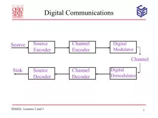
DIGITAL COMMUNICATIONS Part II. Line Coding and Pulse Shaping (Chapter 7). Statement of the Problem. On the way from transmitter to the receiver, we are now here… Two questions: How to pick pulse sequence ? How to pick pulse shape ?s. 1 0 0 1 1. Source encoder. ?. Analog message.

E N D
DIGITAL COMMUNICATIONS Part II Line Coding and Pulse Shaping (Chapter 7)
Statement of the Problem • On the way from transmitter to the receiver, we are now here… • Two questions: • How to pick pulse sequence? • How to pick pulse shape?s 1 0 0 1 1... Source encoder ? Analog message 1999 BG Mobasseri
Picking a pulse sequence:line coding • There are numerous ways we can convert a string of logical 1’s and 0’s to a sequence of pulses. But what are the ground rules? • Example: convert 1 0 1 1 0 1 1 1 1 1 1 1 1 1 OR 0 0 0 0 1999 BG Mobasseri
Line coding concerns • Here are what we have to know before making a selection • Presence or absence of DC level • Spectrum at DC • Bandwidth • Built-in clock recovery • Built-in error detection • Transparency 1999 BG Mobasseri
DC level • Some line codes have a DC level some don’t. DC levels are inherently wasteful of power. Also, their DC levels will be stripped over links with transformers or capacitor coupled repeaters 1 1 1 1 1 1 1 1 0 0 0 0 DC level 0 DC 1999 BG Mobasseri
Spectrum at DC • This is related to the DC level. Generally we want to have the spectrum to be 0 at f=0. Finite spectrum at f=0, indicates partial presence of a DC level 1999 BG Mobasseri
Bandwidth • A most critical component. We must be able to compare the bandwidth taken up by different line codes while transmitting a fixed number of pulses per second. B B 1999 BG Mobasseri
Clock recovery • Knowing the beginning of pulses at the receiver is critical in bit detection. Otherwise you don’t know where you are or what you are looking at. Can you tell where a pulse ends and where the next one begins? Received pulses 1999 BG Mobasseri
Error detection • It is possible to come up with smart pulse sequences that can signal to the receiver there is something wrong • For example, let consecutive 1’s be represented by opposite polarity pulses It is not possible to have two neighboring pulses of the same polarity: It violates the encoding rule There must be a detection error 1 1 1 transmitted channel 1 received 1999 BG Mobasseri
Transparency • Data bits are often random but at times they my bunch up and form unbroken strings of 0’s or 1’s. In such cases statistics of pulse pattern may change • Look at the following two cases: zero DC Non zero DC 1 1 1 1 0 0 0 0 0 0 1999 BG Mobasseri
Specific line codes • We will cover the following line codes • Unipolar • Polar • Split phase or Manchester • Bipolar or AMI (alternate mark inversion) • Coded mark inversion(CMI) • High density bipolar 3 (HDB3) 1999 BG Mobasseri
Unipolar (on-off) • Unipolar (return-to-zero, RZ) • Digit 0 is represented by NO PULSE • Digit 1 is represented by a half width pulse • Unipolar (non RZ) • Digit 0 is represented by NO PULSE • Digit 1 is represented by a half width pulse 1 0 1 0 1999 BG Mobasseri
Unipolar examples • The bit sequence is 1 0 1 1 0 0 0 0 1 0 1 • Unipolar RZ: • Unipolar NRZ: Bit length Half-width pulses Bit length Full width pulses 1999 BG Mobasseri
Unipolar properties by spectral analysis • Let the pulse rate be R. Pulse width is T=1/R Bandwidth=2xpulse rate Bandwidth=pulse rate Clock signals R 2R 0 0 R 2R Unipolar NRZ Unipolar RZ 1999 BG Mobasseri
Could we have predicted the bandwidth? • Nyquist gave us this inequality: BT>R/2, i.e. need at least R/2 Hz to transmit R pulses per sec. • For unipolar we are transmitting R pulses per second. Unipolar spectrum gives us two answers BT=R (NRZ) BT=2R(RZ) 1999 BG Mobasseri
Why the difference? • Nyquist gives us the minimum possible bandwidth. Obviously, neither of the two signaling arrangements reach that goal • The reason is the choice of the pulse shape. We are working with square pulses. To meet Nyquist’s goal, we have to use sinc pulses. More on that later 1999 BG Mobasseri
Importance of clock component • If a unipolar NRZ signal is put through a narrowband bandpass filter centered at R, then a sinusoidal signal emerges that can be used for symbol timing Clock signals 1/R 0 R 2R BPF f 1999 BG Mobasseri
Polar • Encoding rule: • 1 is represented by a pulse • 0 is represented by the negative of the same pulse • Example: encode 1 0 1 1 0 0 0 0 1 0 1 RZ NRZ 1999 BG Mobasseri
Polar spectrum • Identical to unipolar except for the absence of clock component at pulse rate NRZ RZ R 2R 2R 1999 BG Mobasseri
Split phase or Manchester coding • Encoding rule: • 1 is represented by --> • 0 is represented by--> • Encode 1 0 1 1 0 0 0 0 1 0 1 Bit length 1999 BG Mobasseri
Manchester code properties • There are some nice properties here • Zero DC because of half positive/half negative pulses • Transparent: string of 1’s and zeros will not affect DC levels • No DC at f=0 but large bandwidth and no clock R 2R 1999 BG Mobasseri
Bipolar or AMI • Bipolar or alternate mark inversion(AMI) used in PCM is defined by • O ----> no pulse • 1------> ±pulse. Sign of the pulse alternates • Example: 1 0 1 1 1 Alternating polarity 1 1 0 1 1 1999 BG Mobasseri
Advantages • AMI has several nice properties including null at DC. It also avoids signal “droop” over AC coupled lines Result of a long string of 1’s if polar format is used 1999 BG Mobasseri
Bipolar spectrum • Bipolar can be of RZ or NRZ variety. As usual, the NRZ has half the bandwidth of RZ NRZ RZ R R/2 f f 2R 1999 BG Mobasseri
HDBn: G.703 standard for 2,8 and 34 Mbits/sec PCM • High density binaryn line code is just like bipolar RZ with the following modification: • When the number of continuous zeros exceeds n, usually 3, they are replaced by a special code • A string of 4 zeros is replaced by either 000V or 100V. V is a binary 1 with the sign chosen to violate the AMI rule. This will let the receiver know of the substitution 1999 BG Mobasseri
HDB3 example • Le the sequence be 10110000101. Here is the corresponding HDB3 coding 1 0 1 1 0 0 0 0 1 0 1 V Must alternate in polarity 1999 BG Mobasseri
Coded Mark Inversion(CMI):G.703 for 140 Mbits/sec • CMI is a modified polar NRZ code. Pulses corresponding to 0’s stay put but 1’s alternate in polarity. In polar they had a fixed assignment 1 0 1 1 0 0 0 0 1 0 1 1999 BG Mobasseri
CMI spectrum • Similar 3-dB bandwidth to bipolar-NRZ but has a clock component at the pulse rate f R 2R 1999 BG Mobasseri
Pulse Shaping Choosing the right pulse for the job
What is the problem? • What we just went through was about picking a pulse sequence.We have not said anything about the pulse shapes that make up the sequence • Square pulses are by no means the best shapes to use 1999 BG Mobasseri
Criterion for picking pulse shapes • Whatever line coding you choose, the shape of the pulse greatly affects signal properties. The two we are most concerned with are • Bandwidth • Interference with adjacent pulses 1999 BG Mobasseri
ISI:intersymbol interference • Modern communication systems are mostly interference limited, not noise limited • ISI is a phenomenon in digital signaling that arises from the interaction of the signal and communication channel 1999 BG Mobasseri
How is ISI created? • There are a variety of reasons (bandlimited channels, multipath, fading). The end result is something like this 1 0 1 0 1 0 0 0 transmitted 1 0 0 0 1 0 0 0 ISI causes detection error 0’s may look like 1’s and vice versa received 1999 BG Mobasseri
A note on notation • We frequently talk about data rate either in terms of bits/sec(Rb) or pulses/sec(R). They are not the same because one pulse may represent several bits. • Similarly, we may talk about bit length (Tb=1/Rb) or pulse width(T=1/R) • We will use bit notations but results are applicable to pulses as well 1999 BG Mobasseri
Bandlimiting effect • Take square NRZ pulses at Rb bits/sec. The nominal pulse bandwidth is then Rb Hz. • Let’s investigate passage of this pulse through an ideal lowpass channel limited to Rb/2 Hz H(f) ? 1/Rb Rb/2 1999 BG Mobasseri
Output in the frequency domain • In the frequency domain, input is a sinc. receive Rb Rb Rb/2 Clearly, the received pulse is severely bandlimited compared to its original shape. How does it look like in time? transmit 1999 BG Mobasseri
Distorted pulse in time=pulse dispersion • As a result of bandlimiting, we witness pulse “dispersion”, i.e. spreading transmitted received Tb time Tb/2 1999 BG Mobasseri
Notion of sampling instant • A digital receiver works on the basis of samples taken at periodic intervals. • These samples are either taken directly from the pulse (not likely) or after some preprocessing(filtering, equalization) 1999 BG Mobasseri
Dispersion impact on a pulse train • We never send just one pulse. We send a pulse sequence such as 1 1 1... Instead of picking up a sample from the current pulse, we are picking up samples from adjacent samples as well Sampling instants 1999 BG Mobasseri
How to handle ISI? • ISI can be handled at two points, 1): source (by pulse shaping) and /or 2): equalization at the receiver • We will cover both but first look at ISI elimination by pulse shaping 1999 BG Mobasseri
What did Nyquist say about ISI? • He said we need not have zero ISI everywhere. In fact adjacent pulses may have substantial overlap • All we need to have is zero ISI at the sampling points where bit detection is performed 1999 BG Mobasseri
A typical scenario • Detecting bits at the receiver entails two main steps • Sampling of the received signal at the appropriate time • Decision making 0 1 Decision device 1999 BG Mobasseri
Nyquist’s first criterion for zero ISI • Nyquist defined zero ISI as the absence of ISI at sampling instants ONLY. Pulses can overlap each other at all other times with no ill effects 1999 BG Mobasseri
Pulse specification • This is what we want: transmit pulses at the rate of Rb bits/sec such that when the line is sampled at intervals 1/Rb sec., we experience NO ISI • Generally speaking, this is not possible because pulses spread out as they pass through channel 1999 BG Mobasseri
But… there is a way • Of all the candidate pulses, there is one that satisfies this seemingly difficult task. It is , you guessed it, a sinc. • To transmit Rb bits/sec. we should use pulses of the form p(t)=sinc(Rbt) 1999 BG Mobasseri
How does a sinc work? • A sinc pulse has periodic zero crossings. If successive bits are positioned correctly, there will be no ISI at sampling instants. No ISI Nadjacent pulses Go to zero hence no ISI Tb Sampling instants 1999 BG Mobasseri
Another distinction for sinc • We know that sinc(Rbt) has bandwidth of Rb/2 (Fourier table). Therefore, to transmit Rb bits/sec a bandwidth of Rb/2 would suffice • We learned before that this is the minimum transmission bandwidth 1999 BG Mobasseri
Nyquist’s 1st criterion for zero ISI:summary • To transmit data at Rb bits/sec use pulses of the form sinc(Rbt) • In addition to zero ISI, this pulse requires minimum possible bandwidth of Rb /2 1999 BG Mobasseri
Ideal Nyquist channel • Ideal Nyquist channel of bandwidth Rb /2 can support Rb bits/sec • Rb /2 is called the Nyquist bandwidth Nyquist channel 1/Rb Rb/2 1999 BG Mobasseri
Example: PCM voice channel • Remember that to transmit one voice channel, 8-bit PCM generates 64 Kb/sec. Recommend a pulse generating zero ISI • The desired pulse is p(t)=sinc(Rb t)=sinc(64000t) • Required bandwidth is BT=Rb /2=32 KHz 1999 BG Mobasseri