Download
1 / 14
140 likes | 154 Views
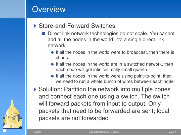
Overview. Store-and-Forward Switches Direct link network technologies do not scale. You cannot add all the nodes in the world into a single direct link network. If all the nodes in the world were to broadcast, then there is chaos.

E N D
Overview • Store-and-Forward Switches • Direct link network technologies do not scale. You cannot add all the nodes in the world into a single direct link network. • If all the nodes in the world were to broadcast, then there is chaos. • If all the nodes in the world are in a switched network, then each node will get infinitesimally small quanta • If all the nodes in the world were using point-to-point, then we need to run a whole bunch of wires between each node • Solution: Partition the network into multiple zones and connect each one using a switch. The switch will forward packets from input to output. Only packets that need to be forwarded are sent; local packets are not forwarded
Scalable Networks • Switch • forwards packets from input port to output port • Each input/output can use different “direct link network” • port selected based on address in packet header • Advantages • cover large geographic area (tolerate latency) • support large numbers of hosts (scalable bandwidth) T3 T3 Switch T3 T3 STS-1 STS-1 Input Output ports ports
Design goals • Switches should increase aggregate throughput • Switches look inside the packet to decide which output port it should place the packet in • Switches look at the destination address • Switches number input and output ports so that they know where to send the packet • Switching strategies: • Datagram: packet carries enough information, along with forwarding/routing tables • Virtual circuit: connection establishment phase • Source routing: packet carries the routing table
Datagram Switching • No connection setup phase • Each packet forwarded independently • Sometimes called connectionless model • Analogy: postal system • Each switch maintains a forwarding (routing) table • Routing table for switch 2: A->3, B->0, C->3, D->3….
Datagram Model • There is no round trip time delay waiting for connection setup; a host can send data as soon as it is ready • Source host has no way of knowing if the network is capable of delivering a packet or if the destination host is even up. • Since packets are treated independently, it is possible to route around link and node failures • Since every packet must carry the full address of the destination, the overhead per packet is higher than for the connection-oriented model
Virtual Circuit Switching • Explicit connection setup (and tear-down) phase • Subsequence packets follow same circuit • Sometimes called connection-oriented model • Analogy: phone call
Message from Host A to Host B • Each switch maintains a VC table • Incoming port 2, Incoming VC 5, Outgoing Interface 1, Outgoing VC 11
Message from Host A to Host B • Virtual circuit numbers are unique per link - I.e., link local
Virtual Circuit Model • Typically wait full RTT for connection setup before sending first data packet. • While the connection request contains the full address for destination, each data packet contains only a small identifier, making the per-packet header overhead small. • If a switch or a link in a connection fails, the connection is broken and a new one needs to be established. • Connection setup provides an opportunity to reserve resources.
Source Routing • Each packet carries the routing information • Source host knows the exact route • Doesn’t scale, but reduces state in switch • Node rotate the address
Maintaining the source route • rotation of route • We will know the reverse path • Stripping • Packets become smaller • Pointer • Each router updates the pointer
A B C Port 1 Bridge Port 2 X Y Z Bridges and Extended LANs • LANs have physical limitations (e.g., 2500m) • Connect two or more LANs with a bridge • accept and forward strategy • level 2 connection (does not add packet header) • Ethernet Switch = Bridge on Steroids
Learning Bridges • Do not forward when unnecessary • Maintain forwarding table • Learn table entries based on source address • Table is an optimization; need not be complete • Always forward broadcast frames
Lab setup • Gateway13-18 are connected to a 8-port Gigabit switch. Itanium servers are connected to a 5 port gigabit switch. The uplink from the 5 port switch is connected to the 8-port switch. The uplink from the 8-port switch is connected to another switch which is connected to ND