Download

1 / 25
250 likes | 269 Views
Explore the design process with simulation, including logic design of an ALU, VPL simulation of gates, testing, and robotics simulation.

E N D
ASU Summer Robotics Camp VPL-Based Simulation Dr. Yinong Chen
Table of Contents Design Process with Simulation 1 Logic Design of an ALU 2 VPL Simulation of Gates 3 Testing 4 Robotics Simulation 5
1 Define Problem 2 Generate Solutions 3 Decide the Course of Action 4 Implement Solution Simulation 5 Evaluate Solution Design Process with Simulation:For Visualizing the Design and for Pre-Evaluation of the Implementation
What is Simulation? • The process of imitating a real phenomenon with a set of mathematical formulas. • Simulation is often based on modeling: Creating mathematical models to imitating real thing. • Advanced computers and programs are the major driving force in creating useful simulations. They can simulate weather conditions, chemical reactions, atomic reactions, even biological processes. • In theory, any phenomena that can be reduced to mathematical data and equations can be simulated on a computer. • In practice, however, simulation is extremely difficult because most natural phenomena are subject to an almost infinite number of influences. • One of the challenges to developing useful simulations is to determine which are the most important factors
Elements of (Propositional) Logic • Proposition: A statement that can either be true or false: • One plus two is three • There is a Nobel prize winner from Arizona State University • The sky is blue • How old are you? • You must ride a bike to school! • Logic connectives • AND (), OR (), NOT (), IMPLIES () • light is on tank is full • (Light is off) (bulb is not broken) tank is empty • Truth and falsity values – Truth Table
a b ab • 0 0 0 • 0 1 0 • 0 0 • 1 1 1 Truth Table as a Specification NOT propositional variable statement a ¬ a false true true false AND a b a b false false false false true false true false false true true true • a a • 0 1 • 0
a b ab • 0 0 0 • 0 1 1 • 0 1 • 1 1 1 Truth Table (Contd.) OR a b a b false false false false true true true false true true true true
a a • 0 1 • 0 • a b ab • 0 0 0 • 0 1 0 • 0 0 • 1 1 1 a b • a b ab • 0 0 0 • 0 1 1 • 0 1 • 1 1 1 a b a c c c NOT gate AND gate c = ab OR gate c = a b c = a a b a b c c NAND gate c = (ab) NOR gate c = (a b) Building Blocks of a Computer Basic Building Blocks Truth Tables • a b (ab) (ab) ab ab • 0 0 1 1 0 • 0 1 1 0 1 • 0 1 0 1 • 1 1 0 0 0 a b c XOR gate c = ab ab
Design my Own Computer? Yes, I can!
ALU Five Modules of a Computer CPU Peripheral Memory Control logic input output Adder Bus
output 8 bits = 1 Byte Can store a “character” Or a short integer 1-bit 1-bit 1-bit 1-bit 1-bit 1-bit 1-bit 1-bit input Memory Design: bit and Byte output 0 1 One bit can store a “1” or a “0” input One-bit memory design
1 byte 1 byte 1 byte 1 byte 1 byte 1 byte 1 byte 1 byte 1 byte 1 byte 1 byte 1 byte 1 byte 1 byte 1 byte 1 byte 1 byte 1 byte 1 byte 1 byte 1 byte 1 byte 1 byte 1 byte 1 byte 1 byte 1 byte 1 byte 1 byte 1 byte 1 byte 1 byte 1 byte 1 byte 1 byte 1 byte 1 byte 1 byte 1 byte 1 byte 1 byte 1 byte 1 byte 1 byte 1 byte 1 byte 1 byte 1 byte 1 byte 1 byte 1 byte 1 byte 1 byte 1 byte 1 byte 1 byte 1 byte 1 byte 1 byte 1 byte 1 byte 1 byte 1 byte 1 byte 1 byte 1 byte 1 byte 1 byte 2 1 0 31 30 29 The Entire Memory, with 32-bit address space and byte-addressable Hex address 00000000h 00000004h 00000008h 0000000Ch 00000010h 00000014h 00000018h 0000001Ch 00000020h 00000024h 00000028h 0000002Ch 00000030h FFFFFFF0h FFFFFFF4h FFFFFFF8h FFFFFFFCh . . . . . . . . . . . . . . .
a a + + sum sum b b carryOut carryOut Designing the Adder 0 a b carryIn 1 0 0 1 0 1 1 + 1 0 1 0 1 1 0 0 1 0 11 0 1 1 1 0 1 1 0 a b carryIn 3 4 5 4 6 1 8 0 7 4 1 0 1 1 0 5 2 6 2 0 . . .
Simulating a One-Bit Adder Use a Computer Program in VPL to imitate the Design Design Testing
a b CarryIn CarryOut Sum sum carryIn a b 0 0 0 0 0 carryOut 0 0 1 0 1 input output 0 1 0 0 1 0 1 1 1 0 1 0 0 0 1 1 0 1 1 0 1 1 0 1 0 1 1 1 1 1 ALU Design: one-bit adder
Simulation in VPL: AND Gate first second output
sum carryIn a b carryOut One-Bit Adder Define Before Using: Define the input whenever you see a warning sign
Define Before Using: Define the input whenever you see a warning sign
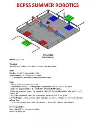
Testing the One-Bit ALU op0 op1 op2 carryIn first second One_Bit_ALU